




If, like me, you are new to developing for the STM32, there are not many tutorials out there on how to get started with certain things. Made worse by the fact that the defaults in ST’s software are not the same as the defaults in their hardware. So, I’ve put together this quick tutorial so I remember how to do this again next time.
First of all you need the STM32CubeIDE software and STM32CubeMX software. The former is a tailor-made IDE and the latter sets up the hardware configuration and initialisation code. You can just use the IDE as this can have CubeMX integrated inside it. But for now I’ve been keeping them separate. From there you can create a project for the STM32F756ZG MPU, unfortunately there is no software template for the board.
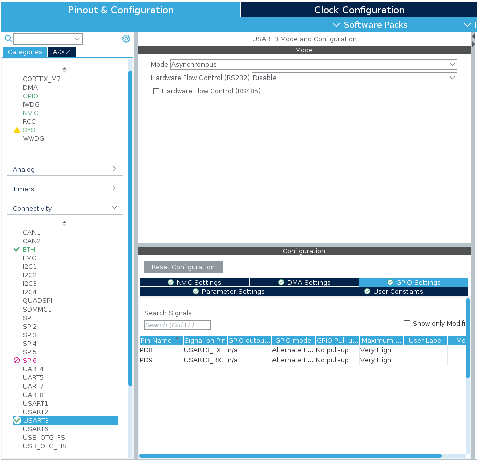
The Nucleo boards include something called ST-LINK which is a USB programmer and debugger for the board. It also includes a couple of extra features such as a UART directly connected to it. In the case of this board, “USART3” is connected and in Linux this corresponds to /dev/ttyACM0 (or a higher number if you already have a ttyACM). There is a gotcha to this, the Nucleo boards do not use the default pins defined in MX for the UART. To get this running, first of all you need to enable it. You can do this by expanding “Connectivity”, clicking on the dropdown for “Mode” and selecting “Asynchronous”:
From here you’ll notice that the pins PB10 and PB11 have been selected, but these are the wrong ones. You actually need to use PD8 and PD9 (as can be seen in the screenshot above). You can change these by finding those pins on the image of the chip, clicking on them and selecting USART3_RX and USART3_TX:
As with the UART, whilst the MX software has everything needed to make the Ethernet work, a few of the defaults are incorrect. You can enable the Ethernet by selecting “ETH” in the “Connectivity” and setting the “Mode” to “RMII”:
The key things to change are the “PHY Address”, it defaults to “1” but for this board it should be “0”. In addition, the pin ETH_TXD0 defaults to PB12 when it should be PG13. This can be seen in the chip image in the UART section above, you can change this in the same way as the UART pins. You might also want to change the MAC address here, although the default will work.
Next we need a mini operating system and network stack. For the OS it is easy to use FreeRTOS. Expand the “Middleware” section and change the “Interface” to “CMSIS_V2“. UPDATE 2021-11-08: CMSIS V2 appears to trigger a bug somewhere that causes memory corruption in the Ethernet code, particularly around the receive semaphore. The fix for this is to choose “CMSIS_V1” instead:
Then click on the “Advanced settings” tab and change “USE_NEWLIB_REENTERANT” to “Enabled”:
When using lwIP you’ll need a larger stack size, which in-turn requires more heap. If you don’t do this then DHCP will handling will blow the stack and crash really fast. I’ve increased the heap here to 128KB:
The stack is set for the individual task, here I’ve increased it to 8KB:
To enable the lwIP network stack simply select “LWIP” in the “Middleware” section and tick the “Enabled” box. For the purposes of this example the defaults are fine. If you want some debugging information then you can turn it on in the “Debug” tab with the “Show Advanced Parameters” checked:
A couple of extra changes that should be made before we hit the “GENERATE CODE” button. First, change the “Timebase Source” to “TIM1” in the “SYS” module. This stops a warning when generating FreeRTOS code:
Finally, in the Project Management tab, we need to set the output “Toolchain” to “STM32CubeIDE” (I also tick “Generate Under Root”). It should be noted that I have “Enable multi-threaded support” ticked here, do not do this. ST’s implementation of lwIP is not thread safe and will crash (typically around 10 minutes into running):
Once you have generated the project and loaded it into the IDE you can make a few changes to main.c so that printf() will output on the UART. The first is intercepting the underlying functions and sending the buffers to the UART, to do this, add the following code between the USER CODE BEGIN PV comments. It is always good to add any additional code in the “USER CODE” sections because these won’t be erased if you make changes in MX later and regenerate the code:
/* Retargets the C library printf function to the USART. */
#include <stdio.h>
#ifdef __GNUC__
int __io_putchar(int ch)
#else
int fputc(int ch, FILE *f)
#endif
{
    HAL_UART_Transmit(&huart3, (uint8_t *)&ch, 1, 0xFFFF);

    return ch;
}
#ifdef __GNUC__
int _write(int file,char *ptr, int len)
{
    int DataIdx;
    for (DataIdx= 0; DataIdx< len; DataIdx++) {
        __io_putchar(*ptr++);
    }
    return len;
}
#endif
Then in the main() function, in the USER CODE BEGIN Init section:
  /* Turn off buffers, so I/O occurs immediately */
  setvbuf(stdin, NULL, _IONBF, 0);
  setvbuf(stdout, NULL, _IONBF, 0);
  setvbuf(stderr, NULL, _IONBF, 0);
Finally we can test this by adding the following in StartDefaultTask() in the USER CODE BEGIN 5 section:
In my test I also turned on some lwIP debugging options so you can see the DHCP happening:
And that is it! You are now free to add more code to use your board on the network, with the ability to use a serial output to debug as needed.
此内容由惯性聚合(RSS阅读器)自动聚合整理,仅供阅读参考。 原文来自 — 版权归原作者所有。