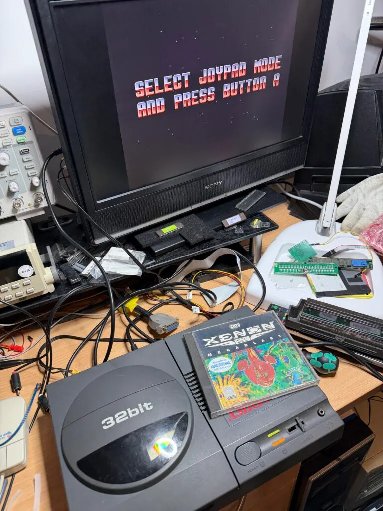





What should have been a straightforward CD32 recap turned into something far more interesting. The CD32 belongs to Tony Warriner, known for Broken Sword and Beneath a Steel Sky, and more recently UrbX Warriors. It turned out to be a bit more work than expected so, of course, I am blogging about it.
I was told that the CD32 powered up, but there was no video output. This is pretty normal, the CD32 by default has video outputs for composite, TV modulator and S-Video. All of these outputs go via a Sony CXA1145 encoder chip, which uses some unique (to Amiga) metal cans for filtering. These cans get destroyed by capacitor leakage. The same thing happens on Amiga 600 and 1200 for composite and TV modulator.
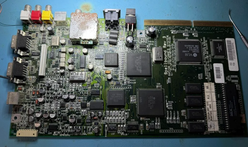
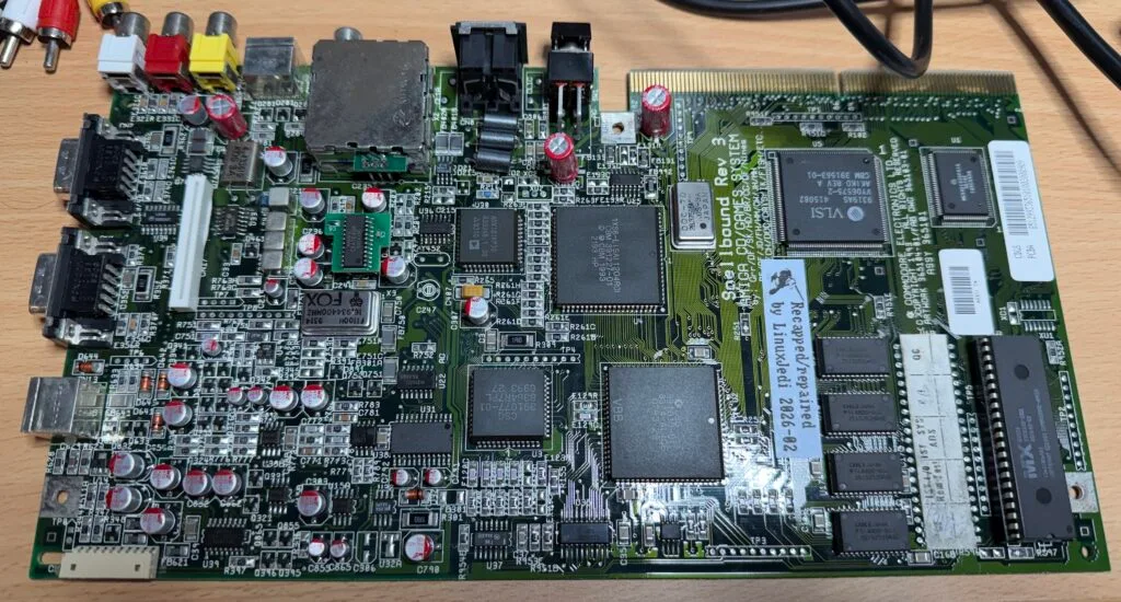
This is the motherboard before I started. There is a lot of dullness on the solder around the video area, which is to be expected. Also, on most CD32s, the through-hole capacitors are soldered backwards, which causes them to bulge and fail.
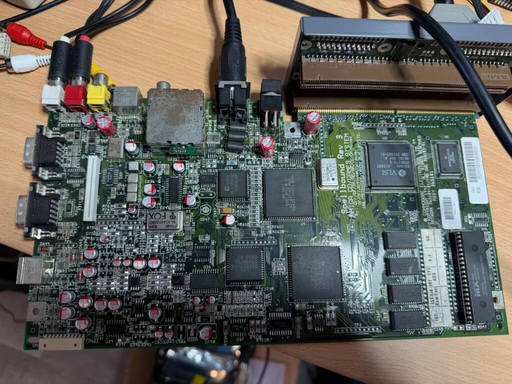
Due to those bulging capacitors, the first thing I do is the recap, before I even test anything. This was relatively straightforward, but the corrosion gave a little bit of a challenge.
Now, although the standard video outputs go via the Sony encoder, I have a module for the expansion port that has a standard Amiga RGB port, and that does not go through that chip. The video on this was working fine.
This is great news! But the other outputs were dead (as expected).
As I’ve mentioned in previous blog posts, I have a repair board for the video encoder. This uses a CXA1645 as well as a special circuit to buffer the audio for the TV modulator. This bypasses the parts of the video circuit that usually fail. Things were better, but not as good as expected.
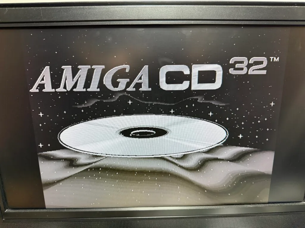
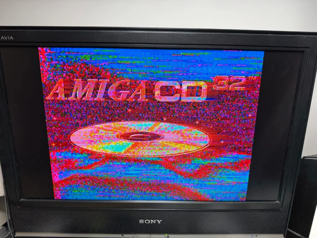
The black and white image was on S-Video and the colour scrambled one was the composite output. This actually helped me figure out the next problem.
There are a couple of things that can cause the colour to go wrong, the first is if the encoder chip is in NTSC mode for a PAL signal. But, if this was the case, I’d expect the composite output to not be like this.
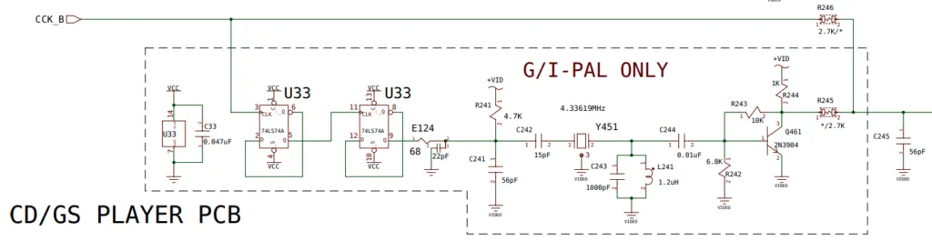
The next is the clock going into the encoder chip. There is a ~4.4MHz clock signal going into the encoder (~3.5MHz for NTSC), and this is used for the colour subcarrier frequency.
The chip uses this clock to:
This means on S-Video, there is luminance, which provides the black and white but the chrominance signal, which provides the colour is missing or corrupted. Also, a bad colour burst signal would cause the composite output to… well, look like that.
This means something in any part of this circuit is bad:
I back-worked my way through this circuit with an oscilloscope and saw just noise all the way, even at U33. Which indicated to me that U33 was bad. This is a D-Type flip-flop which is used to slow down the CCK and the final output is used to trigger the colour clock crystal. This should effectively synchronise the crystal with the rest of the system. This chip was dead.
I replaced this chip and tested again…
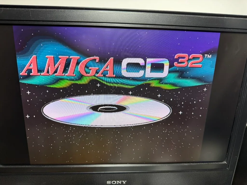
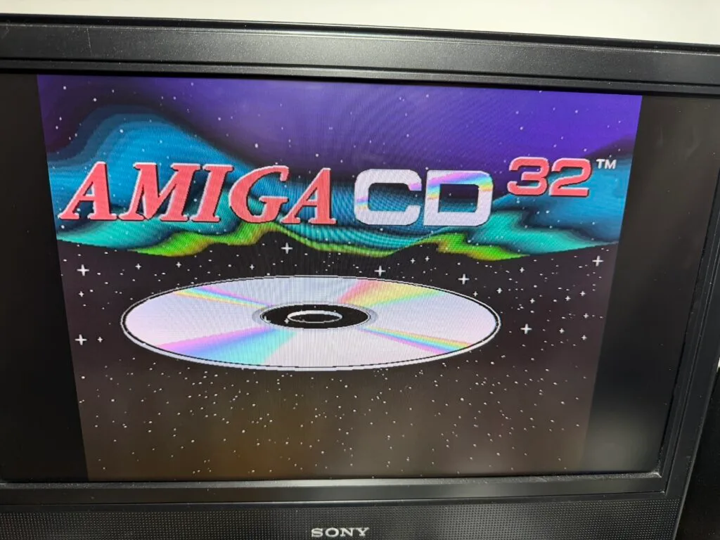
Success! We have a nice colour image now!
With the repair done, I ran the motherboard through an ultrasonic cleaner, reassembled the machine and ran my Xenon II CD in it to test it.
All good, and the machine is ready to go back to Tony!
此内容由惯性聚合(RSS阅读器)自动聚合整理,仅供阅读参考。 原文来自 — 版权归原作者所有。