





Since my work on refraction and chromatic dispersion from early 2023, I have not ceased to experiment with light effects and shaders, always trying to strike the right balance between realism, aesthetics, and performance. However, there's one light effect that I was eager to rebuild this entire time: Caustics.
Those beautiful swirls of light can be visible when light rays travel through a transmissive or transparent curved surface, such as a glass of water or the surface of a shallow lake, and converge on a surface after being refracted. I've been obsessing with Caustics since day one of working with shaders (ask @pixelbeat, he'll tell you). I saw countless examples reproducing the effect on Blender, Redshift, or WebGL/WebGPU, each one of them making me more keen to build my own implementation to fully understand how to render them for my React Three Fiber projects.
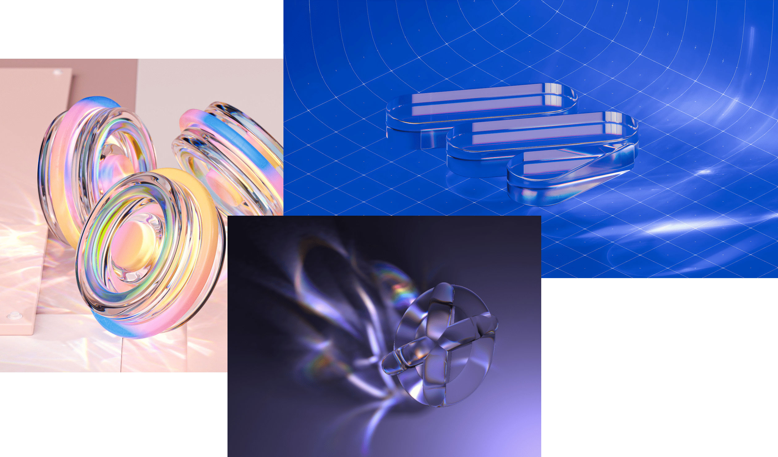
I not only wanted to rebuild a Caustic effect with my shader knowledge from scratch, but I also wanted to reproduce one that was both real-time and somewhat physically based while also working with a diverse set of geometries. After working heads down, step-by-step, for a few weeks, I reached this goal and got some very satisfying results 🎉
While I documented my progress on Twitter showcasing all the steps and my train of thought going through this project, I wanted to dedicate a blog post to truly shine a light on caustics (🥁) by walking you through the details of the inner workings behind this effect. You'll see in this article how, by leveraging normals, render targets, and some math and shader code, you can render those beautiful and shiny swirls of light for your own creations.
In this first part, we'll look at the high-level concepts behind this project. To set the right expectations from the get-go: We're absolutely going to cheat our way through this. Indeed, if we wanted to reproduce Caustics with a high degree of accuracy, that project would probably fall into the domain of raytracing, which would be:
Way out of reach given my current skill set as of writing this article.
Very resource-intensive for the average computer out there, especially as we'd want most people to be able to see our work.
Thus, I opted for a simpler yet still somewhat physically based approach for this project:
We'll simulate in a fragment shader the refracted rays from a light source going through a target mesh.
We'll render the resulting pattern in a caustic plane which we'll then scale and position accordingly based on the position of the light source in relation to our object.
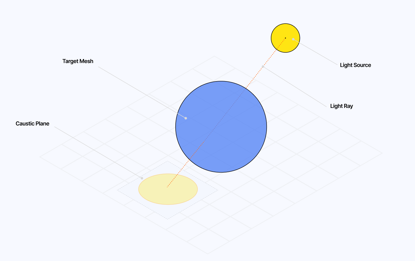
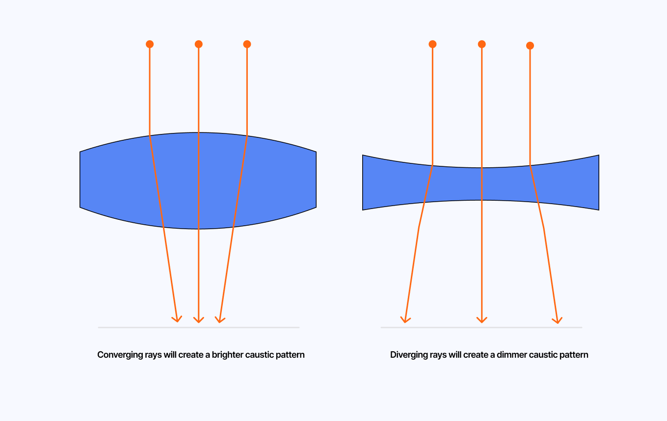
Simulating how the caustic pattern works can seem quite tricky at first. However, if we look back at the definition established in the introduction, we can get hints for how to proceed. The light pattern we're aiming to render originates from rays hitting a curved surface, which nudges us toward relying on the Normal data of our target mesh (i.e. the surface data). On top of that, based on some preliminary research, knowing whether our rays of light converge or diverge after hitting our surface will determine the final look of our caustics.
With what we just accomplished, we have, through our FBO, a texture representing the normals of our target mesh. Having that data as a texture is very versatile because not only can we render it as we just did, but more importantly we can pass it to other shaders to do some computation.
Which is exactly what we're going to do in this part!
We will take our Normal data and simulate light rays going through those normals and then interpret the output to create our caustics pattern.
At first, I didn't know how to use my Normal data to obtain the desired effect as an output. I tried my luck with using a weird mix of sin functions in the fragment shader of my caustic plane, but that didn't yield something even remotely close to what I wanted to achieve:
that's a start I guess 🤔 https://t.co/UCEFoXgrQ1
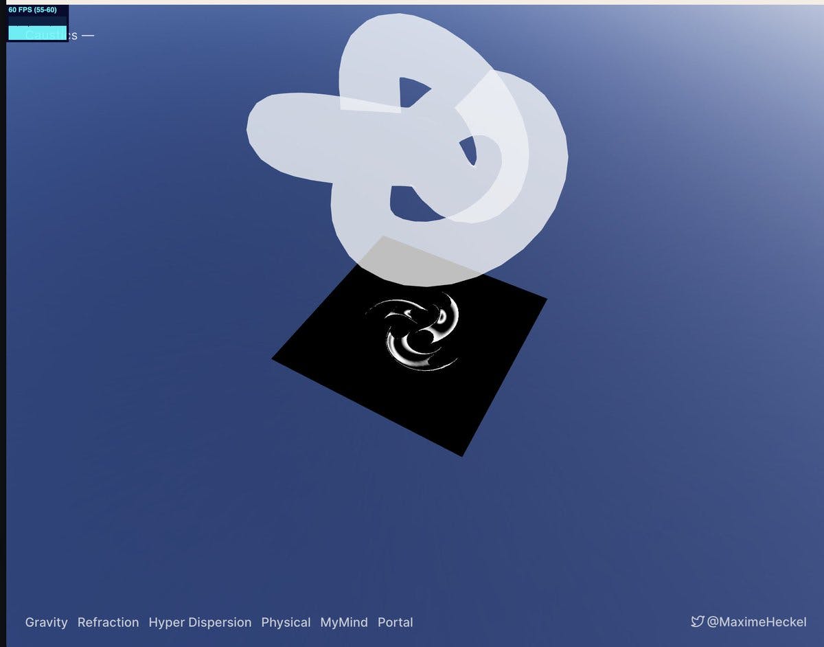
On top of that, I also had this idea for my Caustics effect to be able to take on additional effects such as chromatic aberration or blur, as I really wanted the output not to be too sharp to look as natural as possible. Hence, I could not directly render the pattern onto the final plane; instead, I'd have to use an intermediate mesh with a custom shader material to do all the necessary math and computation I needed. Then, that would allow me through yet another FBO to apply as many effects to the output as I wanted on the final caustics plane itself.
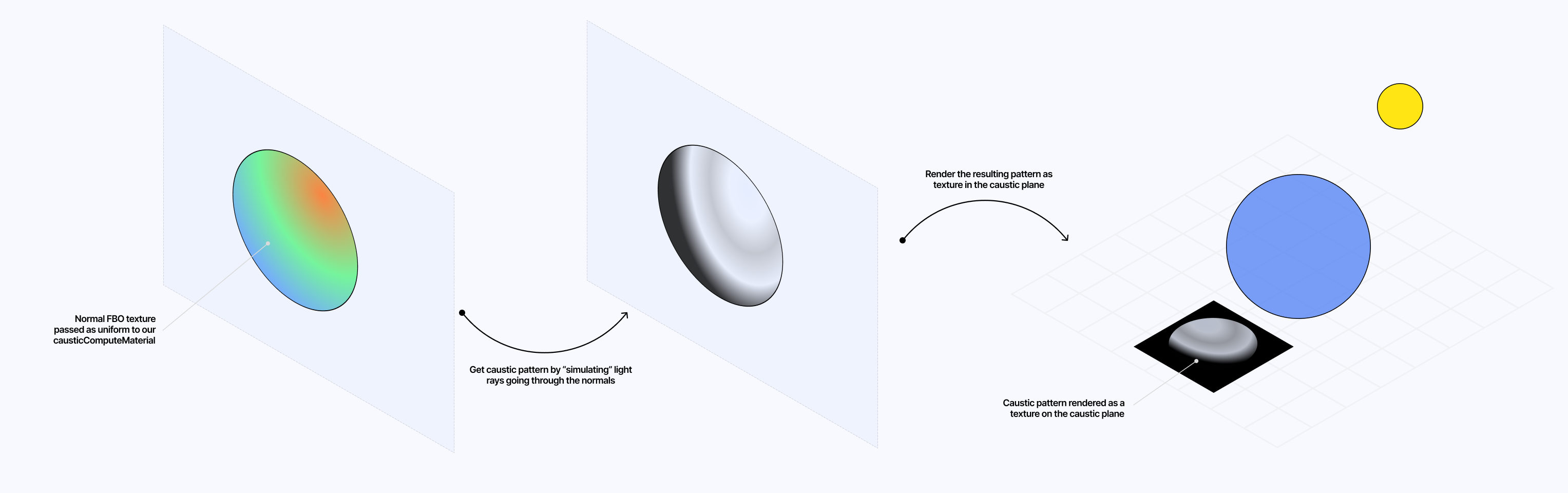
To do so, we can leverage a FullScreenQuad geometry that we will not render within our scene but instead instantiate on its own and use it within our useFrame hook.
Setting up our causticsComputeRenderTarget and FullScreenQuad
1
const causticsComputeRenderTarget = useFBO(2000, 2000, {});
2
const [causticsQuad] = useState(() => new FullScreenQuad());
We then attach to it a custom shaderMaterial that will perform the following tasks:
Calculate the refracted ray vector from our light source going through the surface of our mesh, represented here by the Normal texture we created in the first part.
Apply to each vertex of the FullScreenQuad mesh (passed as varyings to our fragment shader) the refracted ray vector.
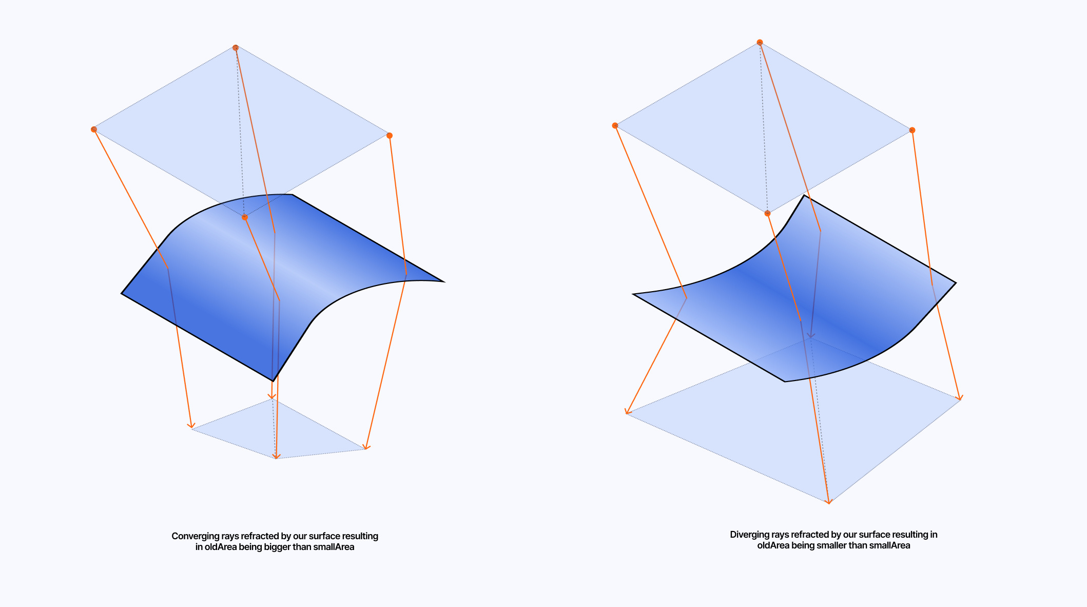
Use partial derivatives along the x and y axes for the original and the refracted position. When multiplied, the result lets us approximate a small surface neighboring the original and refracted vertex.
Compare the resulting surfaces to determine the intensity of the caustics.
Obtaining those surfaces before and after refraction is the key to rendering our caustic pattern:
A ratio oldArea/newArea above 1 signifies our rays have converged. Thus, the caustic intensity should be higher.
On the other hand, a ratio oldArea/newArea below 1 means that our rays have diverged and that our caustic intensity should be lower.
Below, you will find the corresponding fragment shader code that performs the steps we just highlighted:
CausticsComputeMaterial fragment shader
1
uniform sampler2D uTexture;
11
vec3 normalTexture = texture2D(uTexture, uv).rgb;
12
vec3 normal = normalize(normalTexture);
13
vec3 lightDir = normalize(uLight);
15
vec3 ray = refract(lightDir, normal, 1.0 / 1.25);
17
vec3 newPos = vPosition.xyz + ray;
18
vec3 oldPos = vPosition.xyz;
20
float lightArea = length(dFdx(oldPos)) * length(dFdy(oldPos));
21
float newLightArea = length(dFdx(newPos)) * length(dFdy(newPos));
23
float value = lightArea / newLightArea;
25
gl_FragColor = vec4(vec3(value), 1.0);
On top of that, I applied a few tweaks as I often do in my shader code. That is more subjective and enables me to reach what I originally had in mind for my Caustic effect, so take those edits with a grain of salt:
Extra tweaks to the final value from
1
uniform sampler2D uTexture;
3
uniform float uIntensity;
11
vec3 normalTexture = texture2D(uTexture, uv).rgb;
12
vec3 normal = normalize(normalTexture);
13
vec3 lightDir = normalize(uLight);
15
vec3 ray = refract(lightDir, normal, 1.0 / 1.25);
17
vec3 newPos = vPosition.xyz + ray;
18
vec3 oldPos = vPosition.xyz;
20
float lightArea = length(dFdx(oldPos)) * length(dFdy(oldPos));
21
float newLightArea = length(dFdx(newPos)) * length(dFdy(newPos));
23
float value = lightArea / newLightArea;
24
float scale = clamp(value, 0.0, 1.0) * uIntensity;
27
gl_FragColor = vec4(vec3(scale), 1.0);
I added a uIntensity uniform so I could manually increase/decrease how bright the resulting caustic effect would render.
I made sure to clamp the value between 0 and 1 (see warning below).
I squared the result to ensure the brighter areas get brighter and the dimmer areas get dimmer, thus allowing for a more striking light effect.
Finally, we can combine all that and assign what I dubbed the CausticsComputeMaterial to our FullScreenQuad and render it in a dedicated FBO.
Using the causticsComputeMaterial in our scene
1
const [causticsComputeMaterial] = useState(() => new CausticsComputeMaterial());
6
const bounds = new THREE.Box3().setFromObject(mesh.current, true);
8
normalCamera.position.set(light.x, light.y, light.z);
10
bounds.getCenter(new THREE.Vector3(0, 0, 0)).x,
11
bounds.getCenter(new THREE.Vector3(0, 0, 0)).y,
12
bounds.getCenter(new THREE.Vector3(0, 0, 0)).z
14
normalCamera.up = new THREE.Vector3(0, 1, 0);
16
const originalMaterial = mesh.current.material;
18
mesh.current.material = normalMaterial;
19
mesh.current.material.side = THREE.BackSide;
21
gl.setRenderTarget(normalRenderTarget);
22
gl.render(mesh.current, normalCamera);
24
mesh.current.material = originalMaterial;
26
causticsQuad.material = causticsComputeMaterial;
27
causticsQuad.material.uniforms.uTexture.value = normalRenderTarget.texture;
28
causticsQuad.material.uniforms.uLight.value = light;
29
causticsQuad.material.uniforms.uIntensity.value = intensity;
31
gl.setRenderTarget(causticsComputeRenderTarget);
32
causticsQuad.render(gl);
34
causticsPlane.current.material.map = causticsComputeRenderTarget.texture;
36
gl.setRenderTarget(null);
The resulting code lets us observe a glimpse of Caustics projected onto the ground ✨
The result we just obtained looks great but presents a few subjective issues that are bothering me:
It looks a bit too sharp to my taste, and because of that, we also see a lot of artifacts/grain in the final render (probably from the mesh not having enough vertices).
The caustic plane does not blend with the ground: that black frame surrounding the pattern really has to go.
We can alleviate these issues by creating a final causticsPlaneMaterial that takes the texture we obtained from our causticsComputeRenderTarget and gently modifies it before rendering it on our plane.
I first decided to implement a chromatic aberration effect on top of our caustic effect. If you're familiar with some of my work around light effects, I'm a big fan of chromatic aberration, and when applied correctly, I think it really goes a long way to make your scene/mesh look gorgeous.
Refraction and Chromatic Aberration fragment shader
1
uniform sampler2D uTexture;
2
uniform float uAberration;
9
return fract(sin(dot(p.xy ,vec2(12.9898,78.233))) * 43758.5453);
12
vec3 sat(vec3 rgb, float adjustment) {
13
const vec3 W = vec3(0.2125, 0.7154, 0.0721);
14
vec3 intensity = vec3(dot(rgb, W));
15
return mix(intensity, rgb, adjustment);
20
vec4 color = vec4(0.0);
22
vec3 refractCol = vec3(0.0);
24
for ( int i = 0; i < SAMPLES; i ++ ) {
25
float noiseIntensity = 0.01;
26
float noise = random(uv) * noiseIntensity;
27
float slide = float(i) / float(SAMPLES) * 0.1 + noise;
30
refractCol.r += texture2D(uTexture, uv + (uAberration * slide * 1.0) ).r;
31
refractCol.g += texture2D(uTexture, uv + (uAberration * slide * 2.0) ).g;
32
refractCol.b += texture2D(uTexture, uv + (uAberration * slide * 3.0) ).b;
35
refractCol /= float(SAMPLES);
36
refractCol = sat(refractCol, 1.265);
38
color = vec4(refractCol.r, refractCol.g, refractCol.b, 1.0);
40
gl_FragColor = vec4(color.rgb, 1.0);
While this shader worked as expected, it presented some issues: it created visible stripes as it moved each color channel of each texture fragment in the same direction. To work around this, I added code to flip the direction of the aberration through each loop to create some randomness.
Flipping the direction of the chromatic aberration
3
for ( int i = 0; i < SAMPLES; i ++ ) {
4
float noiseIntensity = 0.01;
5
float noise = random(uv) * noiseIntensity;
6
float slide = float(i) / float(SAMPLES) * 0.1 + noise;
8
float mult = i % 2 == 0 ? 1.0 : -1.0;
11
vec2 dir = i % 2 == 0 ? vec2(flip, 0.0) : vec2(0.0, flip);
14
refractCol.r += texture2D(uTexture, uv + (uAberration * slide * dir * 1.0) ).r;
15
refractCol.g += texture2D(uTexture, uv + (uAberration * slide * dir * 2.0) ).g;
16
refractCol.b += texture2D(uTexture, uv + (uAberration * slide * dir * 3.0) ).b;
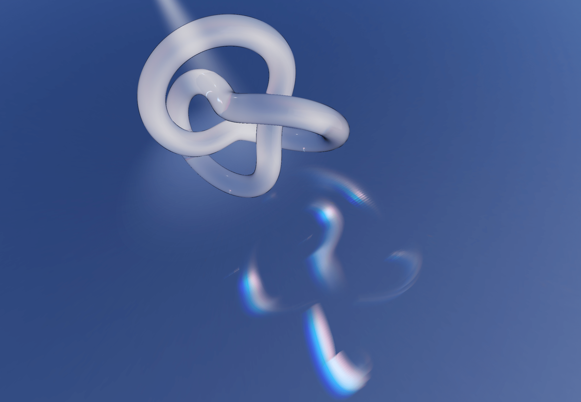
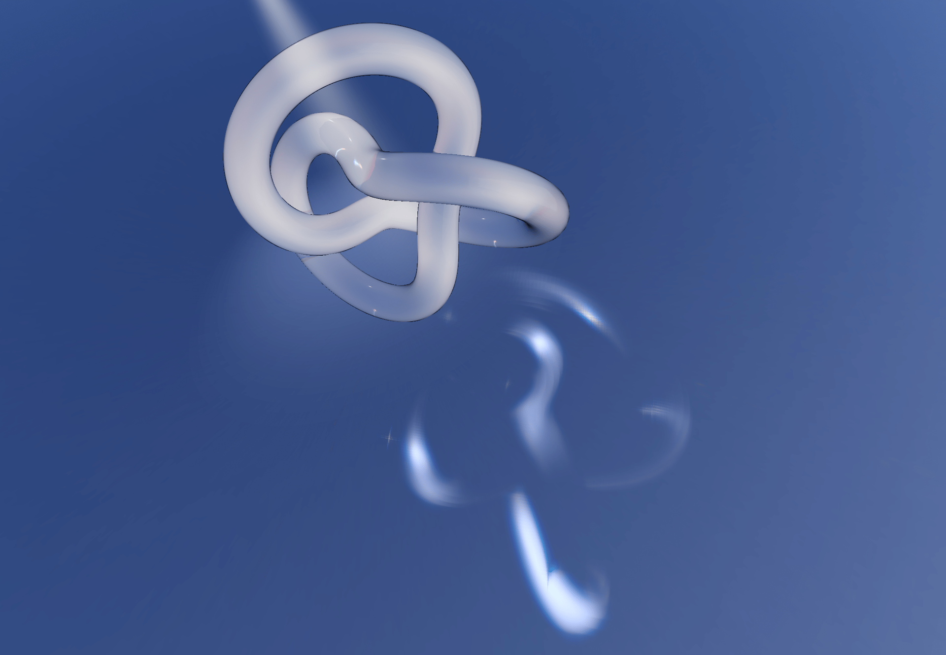
Notice how this simple "flip" operation had multiple benefits:
It solved the issue of the stripes that were degrading the quality of the output.
It blurred the output, making our light patterns less sharp and more natural-looking.
That is what we precisely wanted! Although in some cases, if we look a bit closer, we can see some artifacts from the chromatic aberration, but from afar, it looks quite alright (at least it does to me 😅).
The last thing to tackle is to make our caustic plane blend with the surroundings. We can remove the black frame visible around our light patterns by setting a couple of blending options for our causticsPlaneMaterial after instantiating it:
Setting the proper blending option for our caustic plane to blend in
1
const [causticsPlaneMaterial] = useState(() => new CausticsPlaneMaterial());
2
causticsPlaneMaterial.transparent = true;
3
causticsPlaneMaterial.blending = THREE.CustomBlending;
4
causticsPlaneMaterial.blendSrc = THREE.OneFactor;
5
causticsPlaneMaterial.blendDst = THREE.SrcAlphaFactor;
And just like that, the black frame is gone, and our caustic plane blends perfectly with its surroundings! You can see all the combined code in the code sandbox below 👇.
We now have a convincing caustic effect that creates a pattern of light based on the Normal data of the target mesh. However, if we move the position of our light in the demo we just saw above, the whole scene does not feel natural. That's because we still need to do some work to position and scale our caustic plane based on the position of that light source relative to our mesh.
To approach this problem, I first attempted to project the bounds of our target mesh on the ground. By knowing where on the ground the bounds of our mesh are, I could deduce
The center of the bounds: the vector that we'll need to pass as the position of the caustics plane.
The distance from the center to the furthest projected vertex, which we could pass as the scale of the caustics plane.
Doing this will make sure that the resulting size and position of the plane not only make sense but also fit our caustics pattern within its bounds.
The first step consists of building a bounding cube around our mesh. We luckily did half the work already in the first part of this article when working on getting our Normal data using the following Three.js function:
4
const bounds = new THREE.Box3().setFromObject(mesh.current, true);
The bounds variable contains a min and max field representing the coordinates of the minimum and maximum corners of the smallest cube containing our mesh. From there, we can extrapolate the remaining six corners/vertices of the bounding cube as follows:
Getting the bounds vertices of our target mesh
4
const bounds = new THREE.Box3().setFromObject(mesh.current, true);
6
let boundsVertices = [];
8
new THREE.Vector3(bounds.min.x, bounds.min.y, bounds.min.z)
11
new THREE.Vector3(bounds.min.x, bounds.min.y, bounds.max.z)
14
new THREE.Vector3(bounds.min.x, bounds.max.y, bounds.min.z)
17
new THREE.Vector3(bounds.min.x, bounds.max.y, bounds.max.z)
20
new THREE.Vector3(bounds.max.x, bounds.min.y, bounds.min.z)
23
new THREE.Vector3(bounds.max.x, bounds.min.y, bounds.max.z)
26
new THREE.Vector3(bounds.max.x, bounds.max.y, bounds.min.z)
29
new THREE.Vector3(bounds.max.x, bounds.max.y, bounds.max.z)
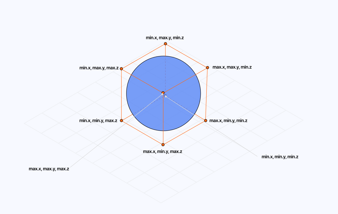
Here, we want to use the vertices of our bounding cube and calculate their projected coordinates in the direction of the light to intersect with the ground.
The generalized formula for such projection looks as follows:
projectedVertex = vertex + lightDir * ((planeY - vertex.y) / lightDir.y)
If we transpose that formula to our code and consider our planeY value to be 0, since we're aiming to project on the ground, we get the following code:
Projected bounding box vertices
1
const lightDir = new THREE.Vector3(light.x, light.y, light.z).normalize();
5
const newVertices = boundsVertices.map((v) => {
6
const newX = v.x + lightDir.x * (-v.y / lightDir.y);
7
const newY = v.y + lightDir.y * (-v.y / lightDir.y);
8
const newZ = v.z + lightDir.z * (-v.y / lightDir.y);
10
return new THREE.Vector3(newX, newY, newZ);
By leveraging the projected vertices, we can now obtain the center position by combining those coordinates and dividing them by the total number of vertices, i.e., just doing a weighted average of all coordinates.
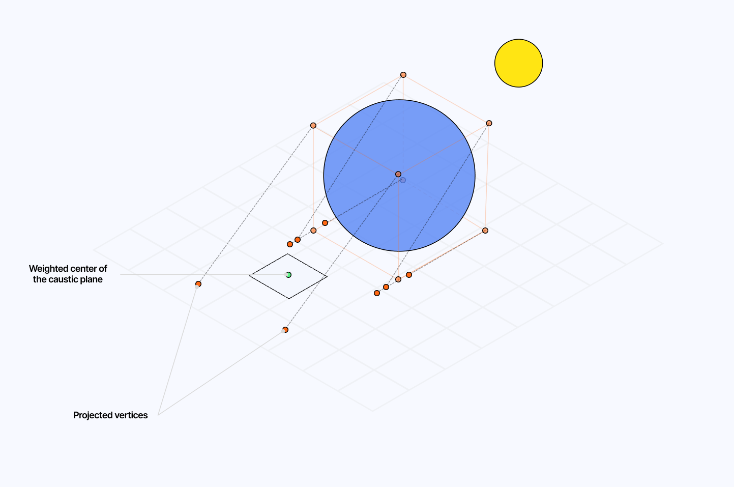
We can then assign that center coordinate as the position vector of our plane, which translates to the following code:
Calculating the weighted center of our caustic plane
1
const centerPos = newVertices
2
.reduce((a, b) => a.add(b), new THREE.Vector3(0, 0, 0))
3
.divideScalar(newVertices.length);
5
causticsPlane.current.position.set(centerPos.x, centerPos.y, centerPos.z);
Now comes the last step of this tedious process: we need to scale our plane so that no matter the position of the light, the resulting caustic pattern always fits in it.
That is tricky, and to be honest the solution I'm about to give you doesn't work 100% of the time, but it covers most of the use cases I encountered, although I could sometimes notice the pattern being subtly cut by the bounds of the plane.
My train of thought to solve this went as follows:
We have the projected vertices.
We got the center position from those vertices.
Hence, we can assume that the safest scale of the plane, the largest that could for sure fit our caustics, should be the distance from the center to the furthest projected vertices.
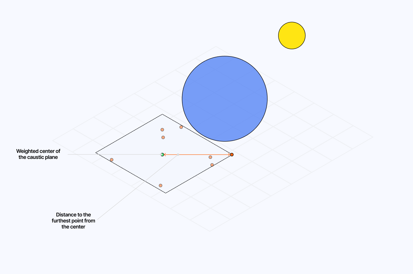
Which can be implemented in code using the Euclidean distance formula:
Calculating the safest scale for our plane to fit the caustic pattern
1
const scale = newVertices
3
Math.sqrt(Math.pow(p.x - centerPos.x, 2), Math.pow(p.z - centerPos.z, 2))
5
.reduce((a, b) => Math.max(a, b), 0);
10
const scaleCorrection = 1.75;
12
causticsPlane.current.scale.set(
13
scale * scaleCorrection,
14
scale * scaleCorrection,
15
scale * scaleCorrection
If we put all this together within our useFrame hook on top of what we've built in the previous part, we finally obtain the long-awaited adjustable caustic pattern ✨.
Our caustic pattern looks gorgeous and behaves as expected as we move the light source around the target mesh! I hope this was worth the trouble so far because there's yet one last thing to explore to make this effect even better...
I would lie to you if I said I wasn't happy with the result above. However, there was still something I wanted to try, and that was to see if the Caustic effect we just built could also handle a moving/displaced mesh and thus feel more dynamic.
On top of that, our effect only really works on shapes that are either very complex or have a lot of intricate, rounded corners, limiting the pool of meshes we can use for a great looking light pattern.
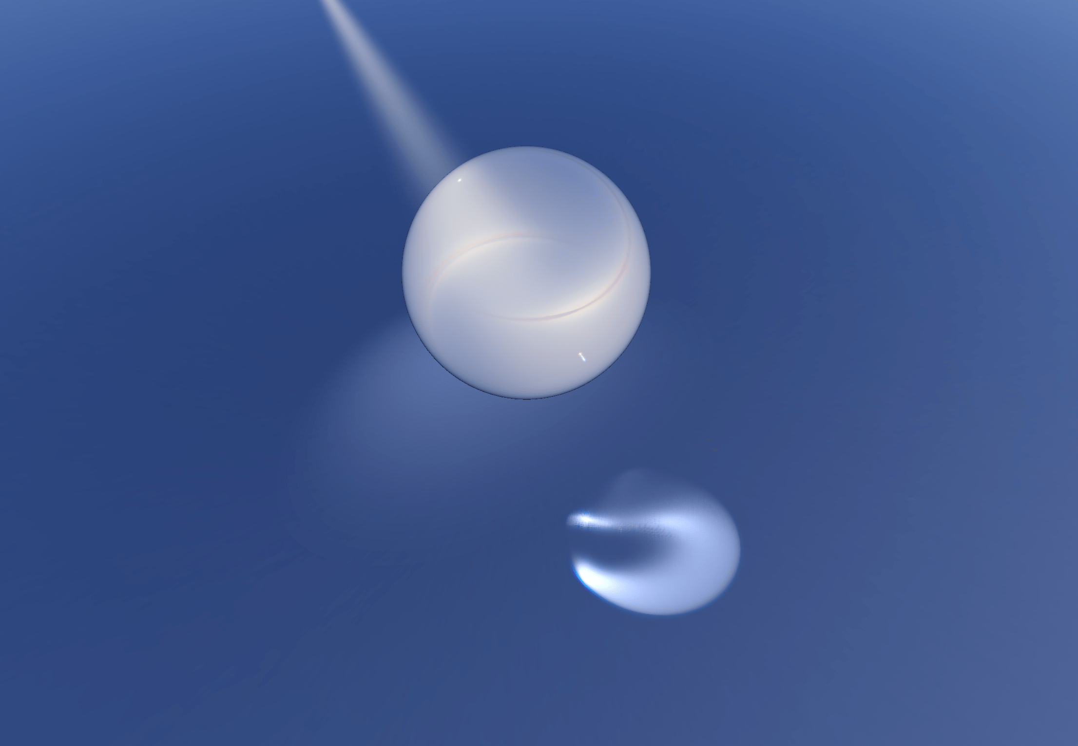
Thus, I had the idea to add a bit of displacement to those meshes to increase their complexity and hope for a better caustic effect. When adding displacement to the vertices of a mesh in a vertex shader, there's one tiny aspect I had overlooked until now: the normals are not recomputed based on the displacement of the vertices out of the box. Thus, if we were to take our target mesh and add some noise to displace its vertices, the resulting Caustic effect would unfortunately remain unchanged.
To solve that, we need to recompute our normals on the fly based on the displacement we apply to the vertices of our mesh in our vertex shader. Luckily, the question of "how to do this" has already been answered by Marco Fugaro from the Three.js community!
I decided to try his method alongside a classic Perlin 3D noise. We can add the desired displacement and the Normal recomputation code to the vertex shader of our original Normal material we introduced in the first part.
Updated Normal material fragment shader
1
uniform float uFrequency;
2
uniform float uAmplitude;
7
vec3 orthogonal(vec3 v) {
8
return normalize(abs(v.x) > abs(v.z) ? vec3(-v.y, v.x, 0.0)
9
: vec3(0.0, -v.z, v.y));
12
float displace(vec3 point) {
14
return cnoise(point * uFrequency + vec3(time)) * uAmplitude;
22
vec3 displacedPosition = position + normal * displace(position);
23
vec4 modelPosition = modelMatrix * vec4(displacedPosition, 1.0);
25
vec4 viewPosition = viewMatrix * modelPosition;
26
vec4 projectedPosition = projectionMatrix * viewPosition;
28
gl_Position = projectedPosition;
30
float offset = 4.0/256.0;
31
vec3 tangent = orthogonal(normal);
32
vec3 bitangent = normalize(cross(normal, tangent));
33
vec3 neighbour1 = position + tangent * offset;
34
vec3 neighbour2 = position + bitangent * offset;
35
vec3 displacedNeighbour1 = neighbour1 + normal * displace(neighbour1);
36
vec3 displacedNeighbour2 = neighbour2 + normal * displace(neighbour2);
38
vec3 displacedTangent = displacedNeighbour1 - displacedPosition;
39
vec3 displacedBitangent = displacedNeighbour2 - displacedPosition;
41
vec3 displacedNormal = normalize(cross(displacedTangent, displacedBitangent));
43
vNormal = displacedNormal * normalMatrix;
Since a time component is required for the noise to move, we need to ensure:
To add a time component to our Normal material. That will influence the entire pipeline we built in the previous parts, down to the final caustic effect.
To add a time component and displacement to the original material. Otherwise, it wouldn't make sense that a static mesh would create moving caustics. (see final example)
Wiring up the target mesh's material and normal material with time, amplitude and frequency to enable dynamic caustics
3
mesh.current.material = normalMaterial;
4
mesh.current.material.side = THREE.BackSide;
6
mesh.current.material.uniforms.time.value = clock.elapsedTime;
7
mesh.current.material.uniforms.uDisplace.value = displace;
8
mesh.current.material.uniforms.uAmplitude.value = amplitude;
9
mesh.current.material.uniforms.uFrequency.value = frequency;
11
gl.setRenderTarget(normalRenderTarget);
12
gl.render(mesh.current, normalCamera);
14
mesh.current.material = originalMaterial;
15
mesh.current.material.uniforms.time.value = clock.elapsedTime;
16
mesh.current.material.uniforms.uDisplace.value = displace;
17
mesh.current.material.uniforms.uAmplitude.value = amplitude;
18
mesh.current.material.uniforms.uFrequency.value = frequency;
We now have wired together all the parts necessary to handle dynamic caustics! Let's take some time to make a beautiful scene with some staging by adding a Spotlight from @react-three/drei and a ground plane that can bounce some light for more realism 🤌 and voilà! We have the perfect scene to showcase our beautiful moving caustics ✨.
Whether you want them subtle, shiny, or colorful, you now know everything about what's behind caustics in WebGL! Or at least, one way to do it! What we saw is obviously one of many possible solutions to building such an effect for the web, and with the advent of WebGPU, I'm hopeful that we'll see more ways to showcase complex light effects like this one with higher quality/physical accuracy and without sacrificing performance. You can already see glimpses of this in one of @active_theory's latest work.
There are a further improvements I had in mind to make the result of this effect look even better, such as getting a texture of the front side and back side normals of the target mesh to take into account both faces when computing the caustic intensity and potentially a more elegant/performant way to do chromatic aberration that is less resource hungry and provides better output.
I'm happy with the caustics I built, although it doesn't seem to result in a beautiful effect for every mesh and I had to resort to last-minute tweaks to fix issues that are most likely due to limitations in my implementation, bad choices in my render pipeline, or simply erroneous math. If you find obvious mistakes: please let me know, and let's work together to fix them! In the meantime, if you wish to have caustics running on your own project, I can't recommend @react-three/drei's own Caustics component enough, which is far more production-grade than the implementation I went through here and will most likely cater to your project much better than this.
I hope this article can spark some creativity in your shader/React Three Fiber work and make the process of building effects or materials you have in mind from scratch less daunting 🙂.
此内容由惯性聚合(RSS阅读器)自动聚合整理,仅供阅读参考。 原文来自 — 版权归原作者所有。
