








//////////////////////////////////////////////////////////////////////
// Created by Microsemi SmartDesign Fri Apr 24 14:20:16 2026
// Testbench Template
// This is a basic testbench that instantiates your design with basic
// clock and reset pins connected.  If your design has special
// clock/reset or testbench driver requirements then you should
// copy this file and modify it.
//////////////////////////////////////////////////////////////////////

///////////////////////////////////////////////////////////////////////////////////////////////////
// Company: <Name>
//
// File: uart_rx_testbench.v
// File history:
//      <Revision number>: <Date>: <Comments>
//      <Revision number>: <Date>: <Comments>
//      <Revision number>: <Date>: <Comments>
//
// Description:
//
// <Description here>
//
// Targeted device: <Family::ProASIC3> <Die::A3P250> <Package::100 VQFP>
// Author: <Name>
//
///////////////////////////////////////////////////////////////////////////////////////////////////

`timescale 1ns/100ps

module uart_rx_testbench;

parameter SYSCLK_PERIOD = 25;// 40MHZ

reg SYSCLK;
reg NSYSRESET;

initial
begin
    SYSCLK = 1'b0;
    NSYSRESET = 1'b0;
end

//////////////////////////////////////////////////////////////////////
// Reset Pulse
//////////////////////////////////////////////////////////////////////
initial
begin
    #(SYSCLK_PERIOD * 1 )
        NSYSRESET = 1'b1;
end


//////////////////////////////////////////////////////////////////////
// Clock Driver
//////////////////////////////////////////////////////////////////////
always @(SYSCLK)
    #(SYSCLK_PERIOD / 2.0) SYSCLK <= !SYSCLK;


// sysclk 计数 方便观察时序
reg [31:0] clk_cnt;
always @(posedge SYSCLK or negedge NSYSRESET) begin
    if( !NSYSRESET ) begin
        clk_cnt <= 32'b0;
    end else begin
        clk_cnt <= clk_cnt + 32'b1;
    end
end

// 常用宏定义
// i_ input 信号
// o_ output 信号
// r_ reg  信号
// w_ wire 信号
// t_ trigger 信号
parameter TRUE  = 1'b1;
parameter FALSE = 1'b0;

// 测试串口接收处理模块

wire w_rx_oen;
reg [7:0] r_rx_data;
reg r_rx_ready;

uart_rx uart_rx_0
(
    .clk_40mhz(SYSCLK), // 时钟和复位信号 都是输入信号,因此不加 i_
    .rst_n(NSYSRESET),

    // UART RX
    // 低电平将 DATA_OUT 读入, 将  RXRDY 和 所有错误复位 ,溢出和校验错误 复位
    .o_rx_oen(w_rx_oen),
     // 输出数据总线 位宽 [7:0]
    .i_rx_data(r_rx_data),
    // 0= RX FIFO 空, 1= 可读取
    .i_rx_ready(r_rx_ready)

);


// 编写串口数据
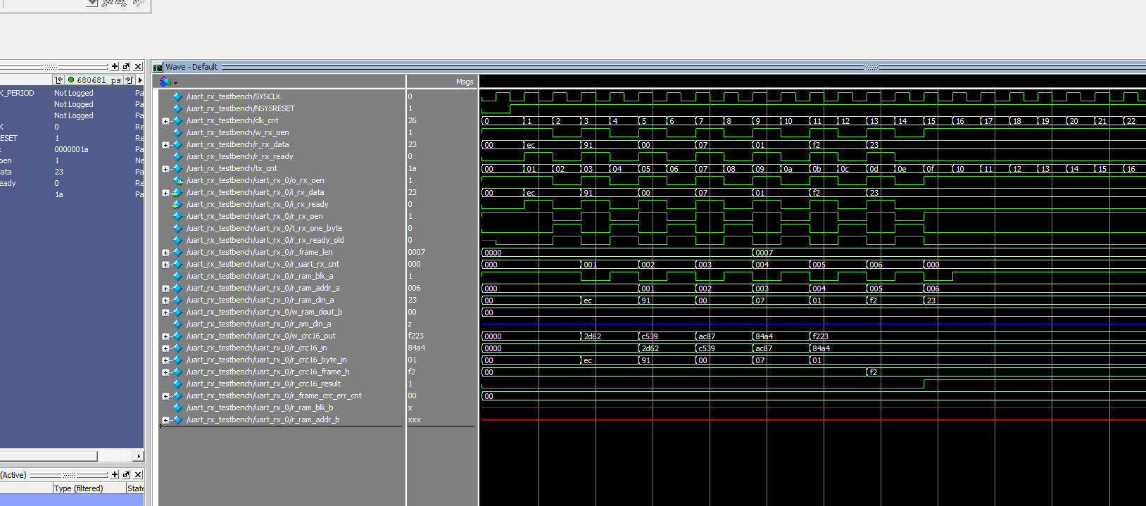
reg [7:0] tx_cnt;
always @(posedge SYSCLK or negedge NSYSRESET) begin
    if( !NSYSRESET ) begin
        r_rx_data <= 8'd0;
        r_rx_ready <= FALSE;
        tx_cnt <= 8'd0;
    end else begin
        tx_cnt <= tx_cnt + 8'd1;

        case(tx_cnt)
            0: begin
                r_rx_data <= 8'hEC;
                r_rx_ready <= TRUE;
            end
            1: begin
                r_rx_ready <= FALSE;
            end
            2: begin
                r_rx_data <= 8'h91;
                r_rx_ready <= TRUE;
            end
            3: begin
                r_rx_ready <= FALSE;
            end
            4: begin
                r_rx_data <= 8'h00;
                r_rx_ready <= TRUE;
            end
            5: begin
                r_rx_ready <= FALSE;
            end
            6: begin
                r_rx_data <= 8'h07;
                r_rx_ready <= TRUE;
            end
            7: begin
                r_rx_ready <= FALSE;
            end
            8: begin
                r_rx_data <= 8'h01;
                r_rx_ready <= TRUE;
            end
            9: begin
                r_rx_ready <= FALSE;
            end
            10: begin
                r_rx_data <= 8'hF2;
                r_rx_ready <= TRUE;
            end
            11: begin
                r_rx_ready <= FALSE;
            end
            12: begin
                r_rx_data <= 8'h23;
                r_rx_ready <= TRUE;
            end
            13: begin
                r_rx_ready <= FALSE;
            end
            default: begin
                r_rx_ready <= FALSE;
            end
        endcase

    end
end

endmodule
此内容由惯性聚合(RSS阅读器)自动聚合整理,仅供阅读参考。 原文来自 — 版权归原作者所有。