







I have a camera gear collection problem and as part of my personal 12 step plan, I restrict myself from purchasing functioning lenses. This sounds illogical, and it frankly is, but it's very hard for me to resist heavily discounted lenses. To keep my hat, I tend to only bid on lenses that are less than 1/4 of the going used sale prices and have little to no mechanical damage. In this case I've been eyeing the recently produced sigma I-series lenses that feature mostly aluminum construction. A broken 45mm f/2.8 lens popped up on ebay in January for a song and a dance, and I simply could not resist.
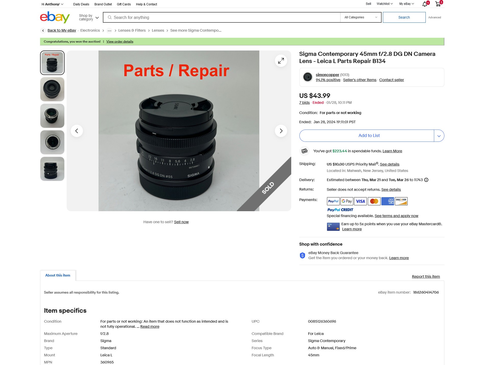
The auction was listed by an ebay seller that tends to have regular inventory of broken modern camera gear which is great from a repair perspective. Occasionally the seller will teardown equipment and sell parts, leaving me a bit uneasy about the internal state of the listed items for sale, but I took a chance and went with it.
The lens came well packaged and on initial inspection, featured zero mechanical flaws. No scratches on the barrel or lens elements whatsoever. To properly inspect the outer lens elements, I use my oil free air compressor and thoroughly blow off any debris from the lens and properly clean both front and rear element with a kimwipe and lens cleaning solution. Eye glasses cleaner from the drug store is adequate for most external lenses. Isopropyl alcohol is another good alternative, but don't use on plastic lenses.
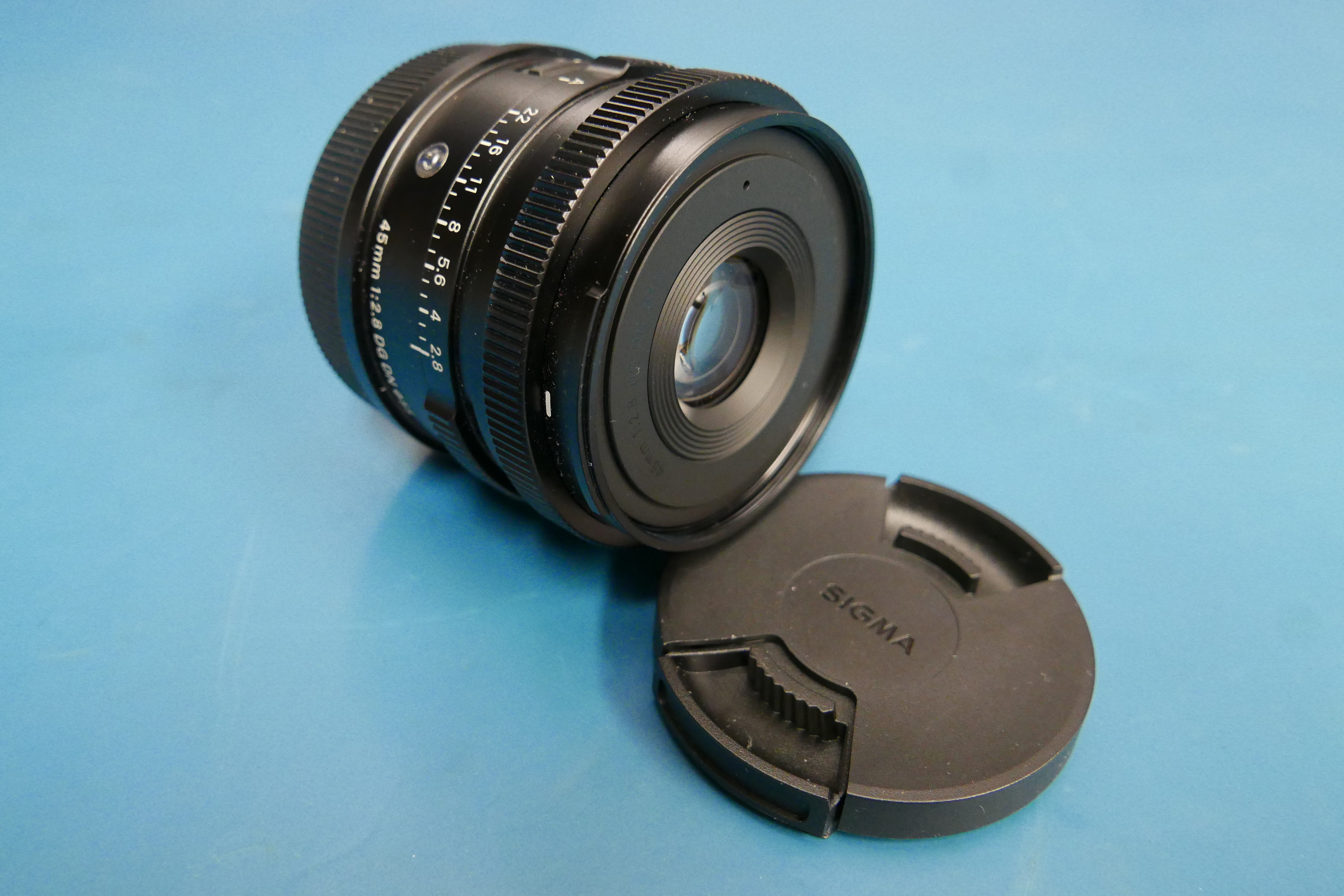
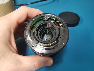
I mounted the lens to my Lumix S5 and with seemingly too much force, it clicked into place. The camera booted up fine and even displayed a live image, but no electronic controls worked whatsoever. None of the dials or switches on the lens responded to user input. The control dials on the camera did not register movement. Clearly, there was something electrically wrong with the lens. The control PCB is usually found on the rear of the lens nearest to the rear lens contact block. It would also provide a good time to investigate the very stiff lens mount.
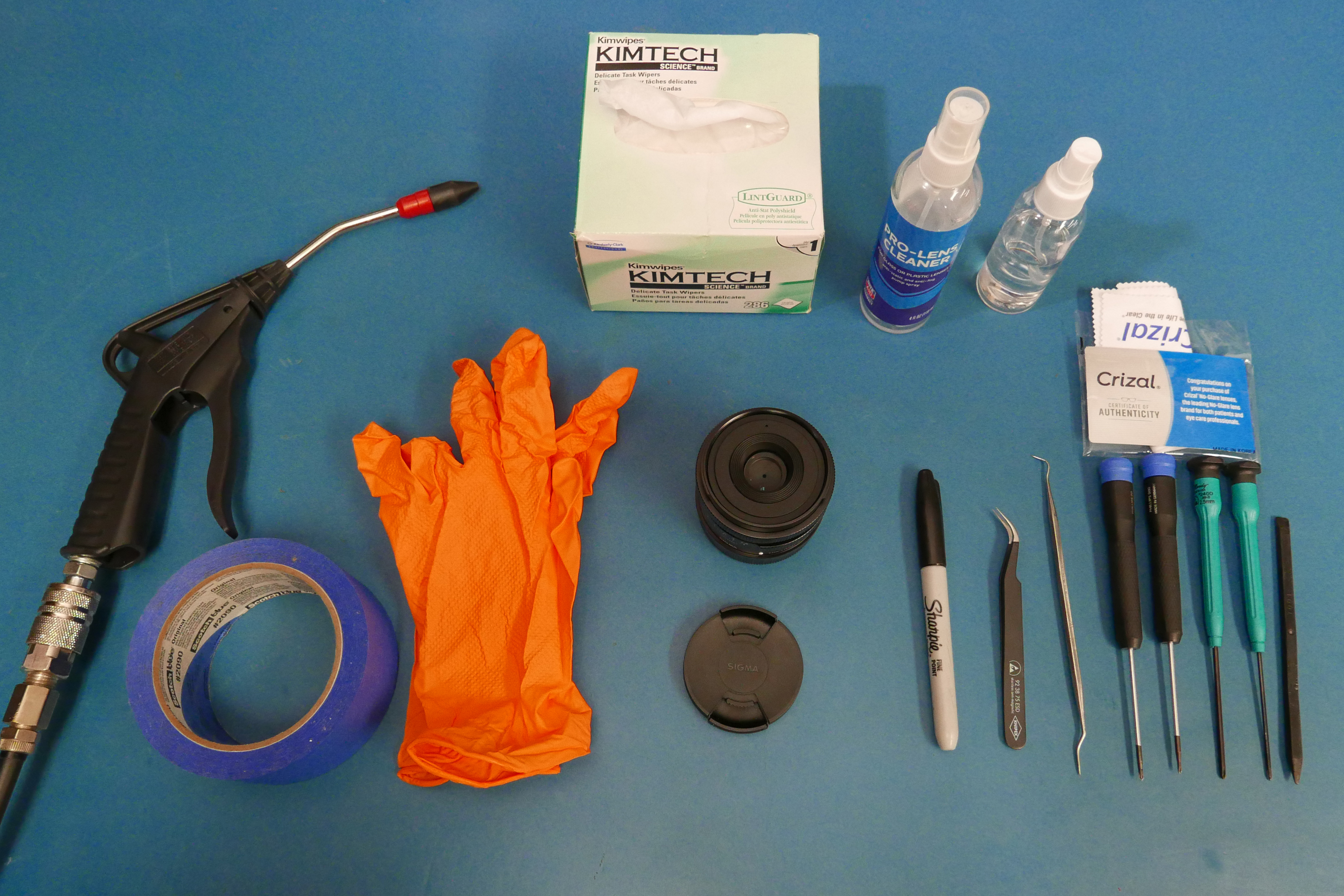
The barriers to entry on this repair are low. Most of these tools are pretty standard and generic at this point. The biggest expense besides the lens is filtered air, but even a compressed air duster can suffice. Note: Since most of the camera industry design folks are centered in Japan, the JIS screw is standard. Using a Phillips will work but it tends to wear down the heads on the JIS screws faster. Here are some of my go-to tools:
For disassembly, I orient the lens with the aperture mark facing me and the table front edge. The rear plastic beauty spacer around the rear element is removed first along with (3) black machine screws. Following, the two nickel plated screws that fixture the side of the plastic lens block terminal interface to the metal lens mount are removed. The screws are placed on double sided tape in an orientation that matches the lens orientation. This makes future reassemble substantially easier.
Next order of business, the lens mount bayonet and shims. The orientation and order of these shims matter so they deserve their own bit of tape. This lens had trouble mounting to a camera body so I thoroughly inspected the shims, bayonet mount back and the lens body for imperfections and surface contamination. I cleaned all surfaces with ipa and moved on. Note: be extra careful when handling the lens contact block flex cable.
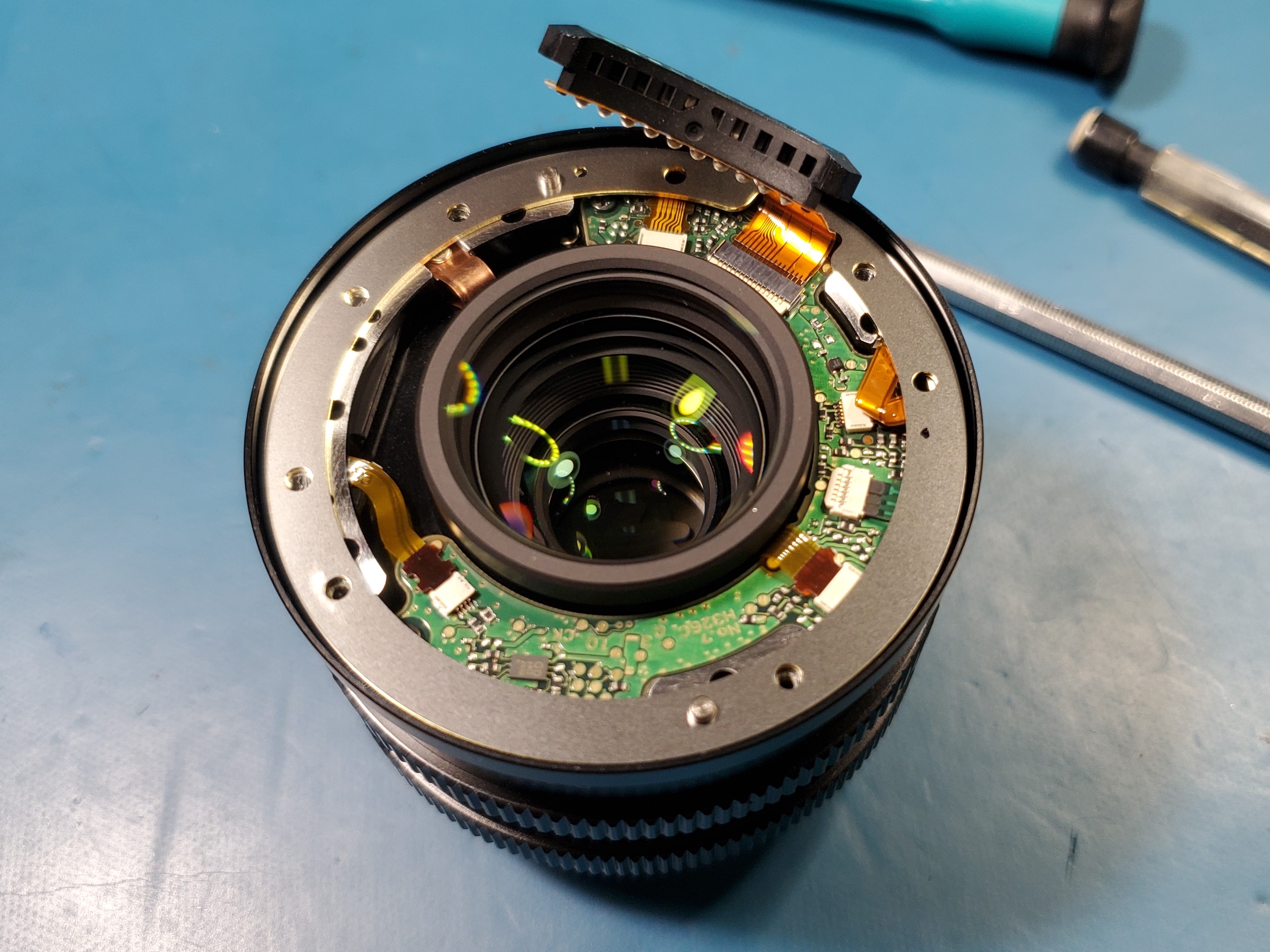
At this point in the disassembly, the lens contact block can be freely removed from the control PCB. The contact block for L-mount features 10 terminals that connect to the control PCB via a flexible polyimide cable. This flex cable has a tendency to tear easily, especially if not handled carefully. Before continuing further with the teardown, take a multimeter and check the continuity of each trace. If there are visible tears in the flex cable, repair that first before continuing to diagnose any problems. I have another guide on how to make your own flex cables here. The flex cable metered out to be flawless, so I proceeded the teardown.
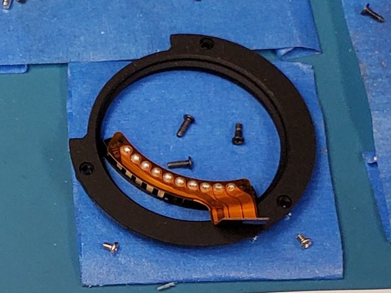
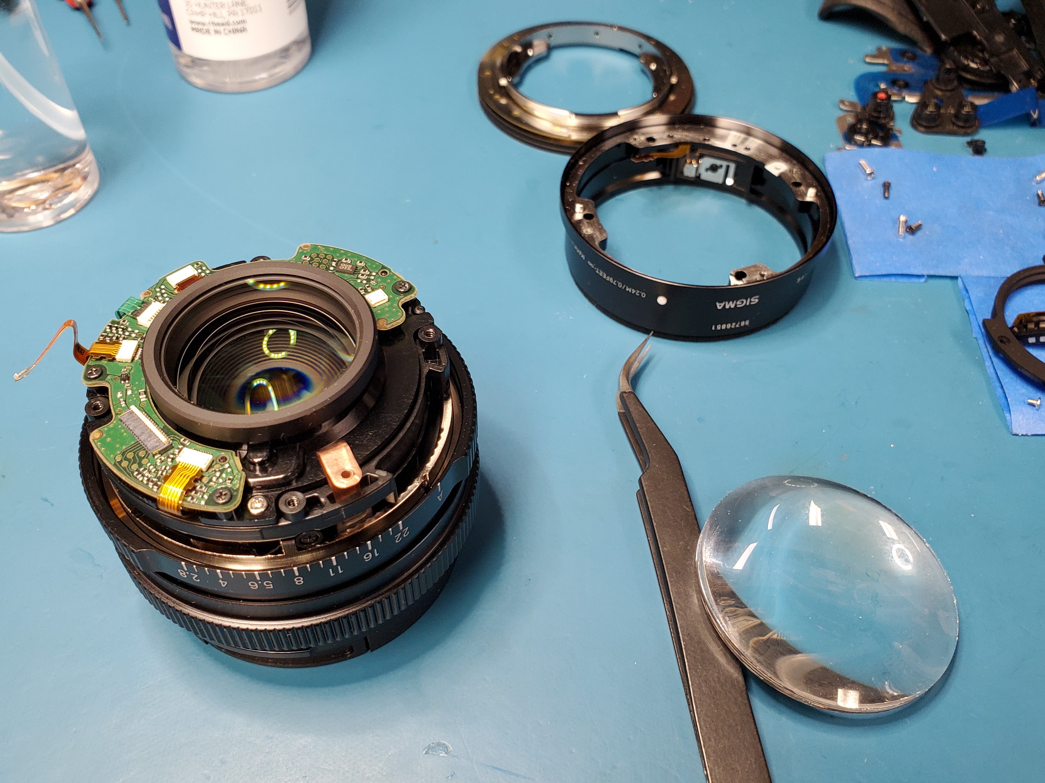
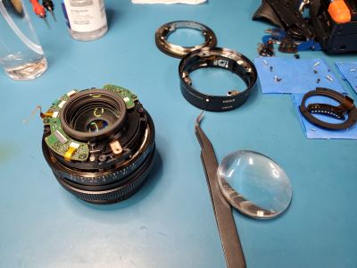
The rear CNC machined aluminum shell of the lens is up next. Two grounding straps are fixtured to the rear shell using nickel plated machine screws. The straps are oriented around the 2pm and 7pm clock position. A push-in switch flex connector is positioned around the 11pm position that can be wiggled out using a pair of tweezers. There are (4) black oxide self tapping screws that mate the shell to the center plastic lens module. The rear shell can now be safely lifted up and set aside, with the aperture mark positioned toward the table edge.
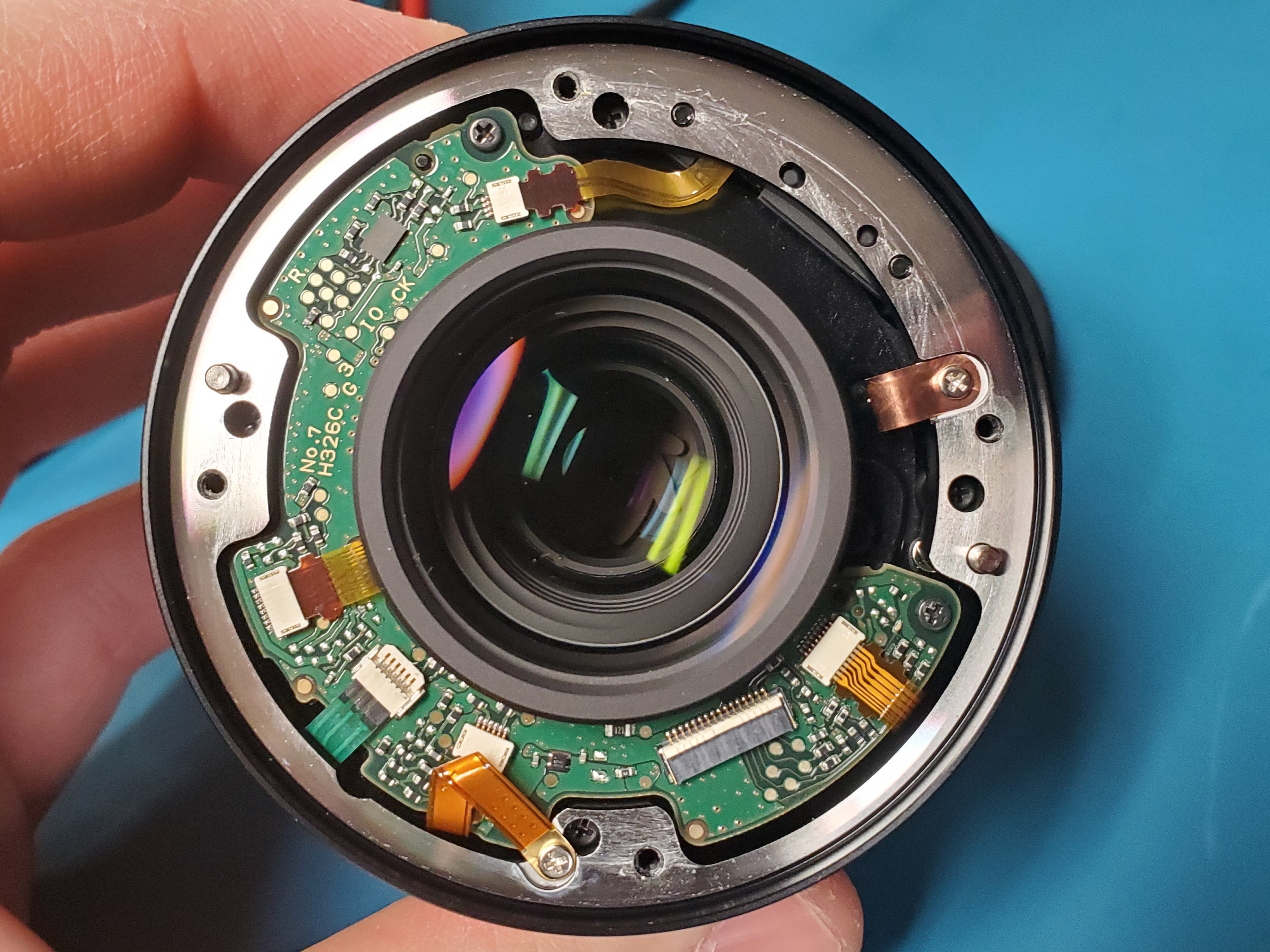
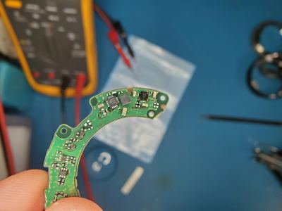
The control PCB and remainder of the flex cables are now easily accessible. Three black self tapping screws mate the PCB to the plastic lens module at the 2pm, 7pm, and 10pm clock position, respectively. Once the flex cables are wiggled loose, the control PCB can be freed from the lens body and more closely scrutinized.
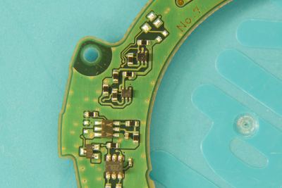
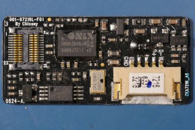
The C-shaped PCB looks right at home with the dozens of other lens control PCBs I've analyzed. There's a main microcontroller, DC-DC controller, motor controller, crystal oscillator, and a slew of passives.
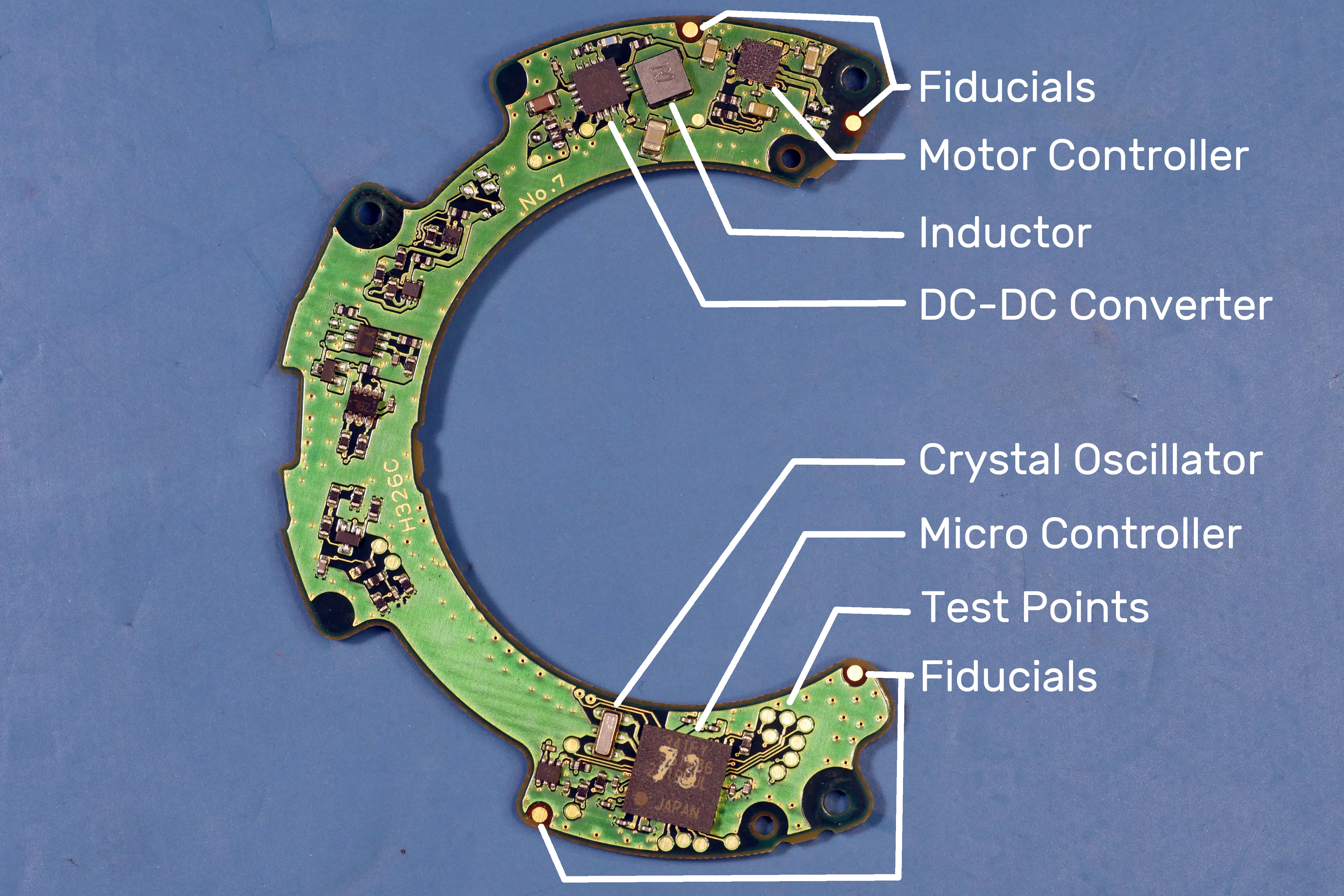
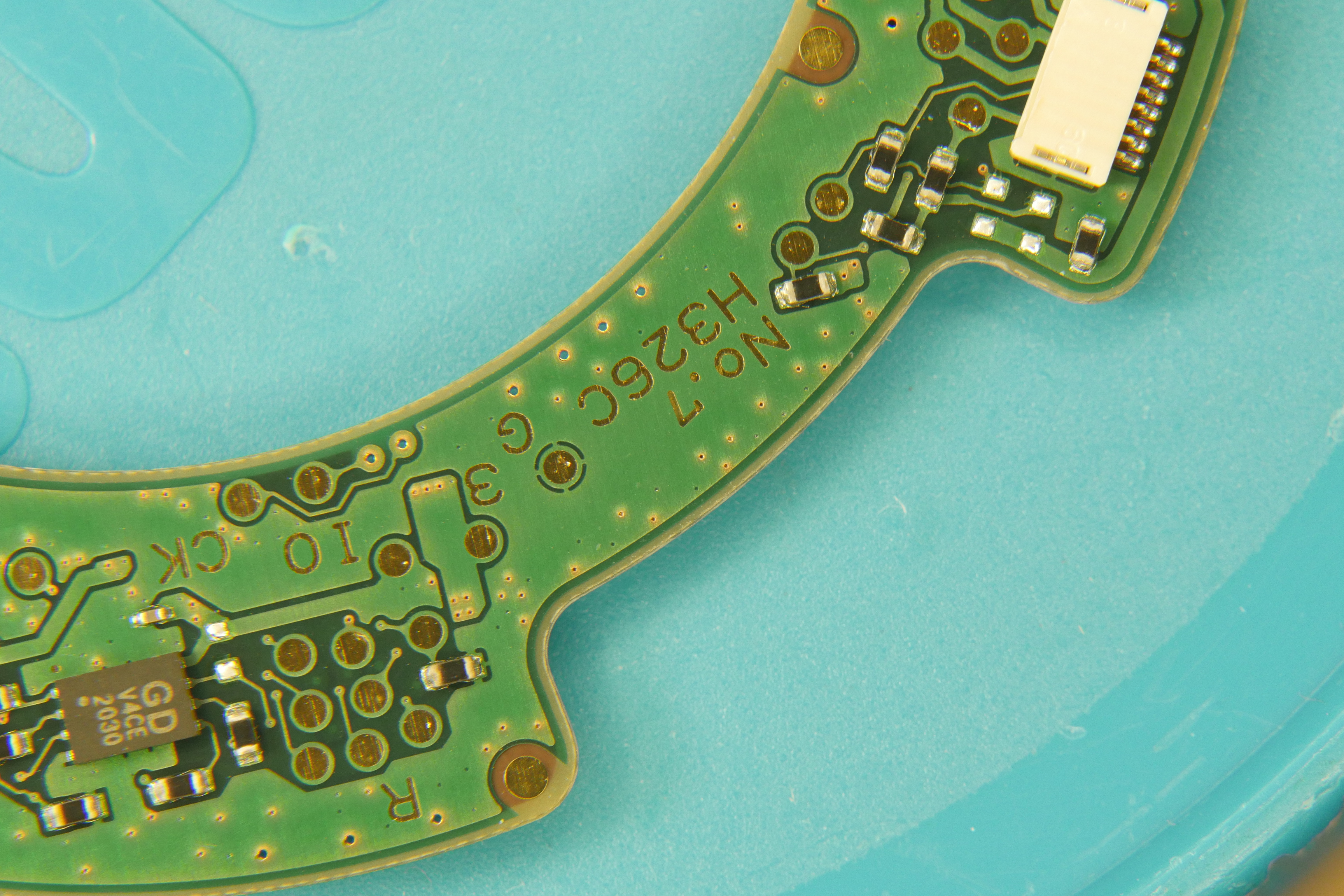
The reverse side is adorned with FPC (Flexible Printed Circuit) connectors, test points and an 8-pin SPI flash package directly below the main microcontroller.
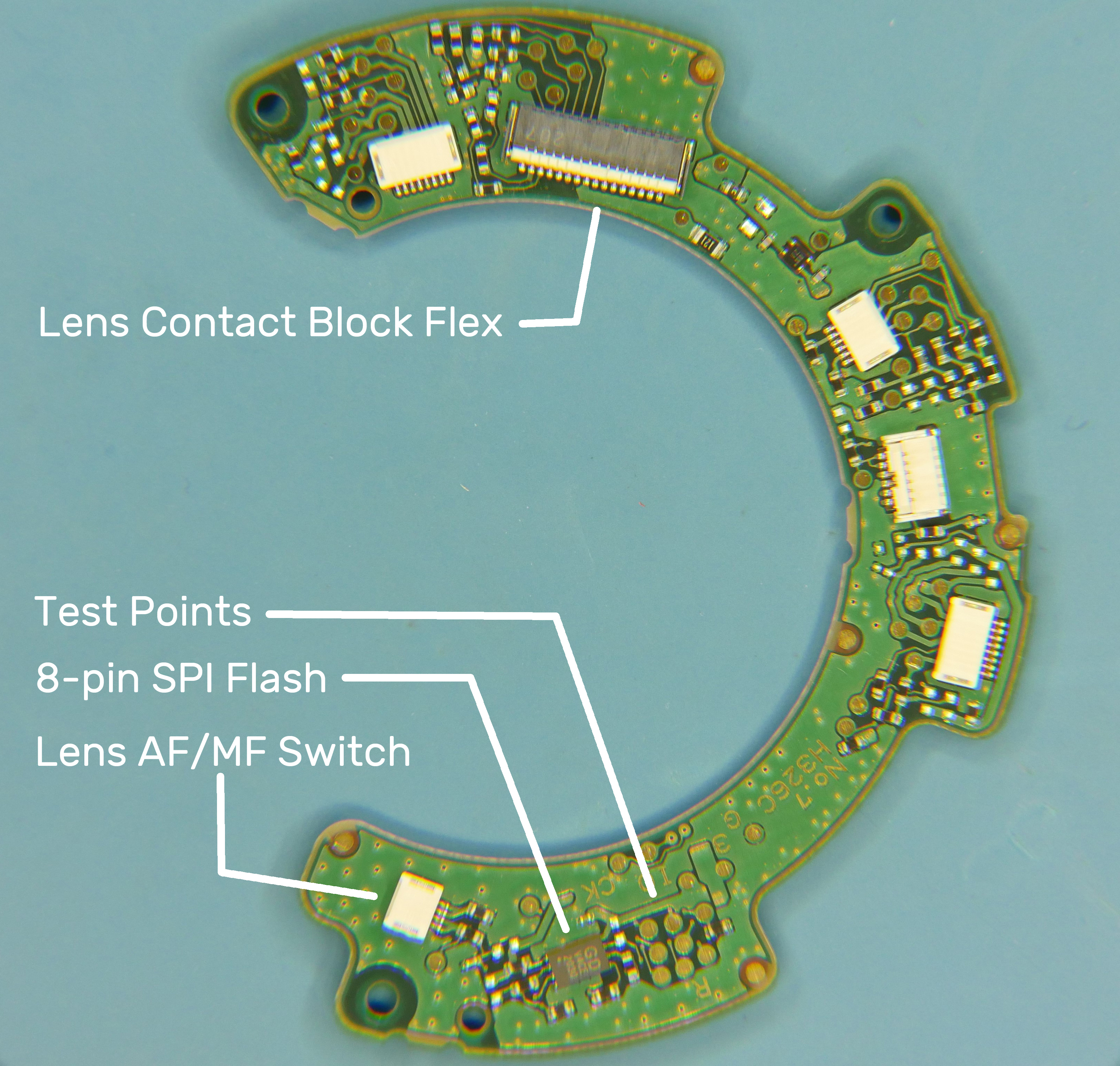
Inspecting any unknown PCB for faults can be quite intimidating, but I find it easiest to start with tracing the input power lines first. Where is this board supposed to receive power from? Where do the V+ and Gnd traces first begin on the PCB? What is the first component that receives power on the board? PCBs can be a very complicated mess of layers and jumped traces, so feel free to write down simplified schematic notes on scrap paper to keep a simple PCB power order-of-operations.
To start, trace the input power from the lens terminal block. The thicker flex PCB traces are most definitely V+ and Gnd. Follow those traces on the PCB and use the continuity mode of your multimeter to find out where the power traces on the PCB lead to. In this case, tracing the input power is tricky because the large traces associated with the flex cable are hidden beneath the FPC connector and passed through the PCB to the opposite side through vias. The power traces were then fed to a small square black chip, a staple in small scale electronics: the DC-DC converter.
A telltale sign of a DC-DC controller is the presence of an adjacently placed properly-chunky tan, beige or black colored block that dwarfs the size of the power controller. The photo below indicates a circled "2R2" or a 2.2 uH (micro Henry) inductor. This close proximity inductor arrangement is universally recommended by semiconductor manufacturers in effort to reduce radiated emissions / noise.
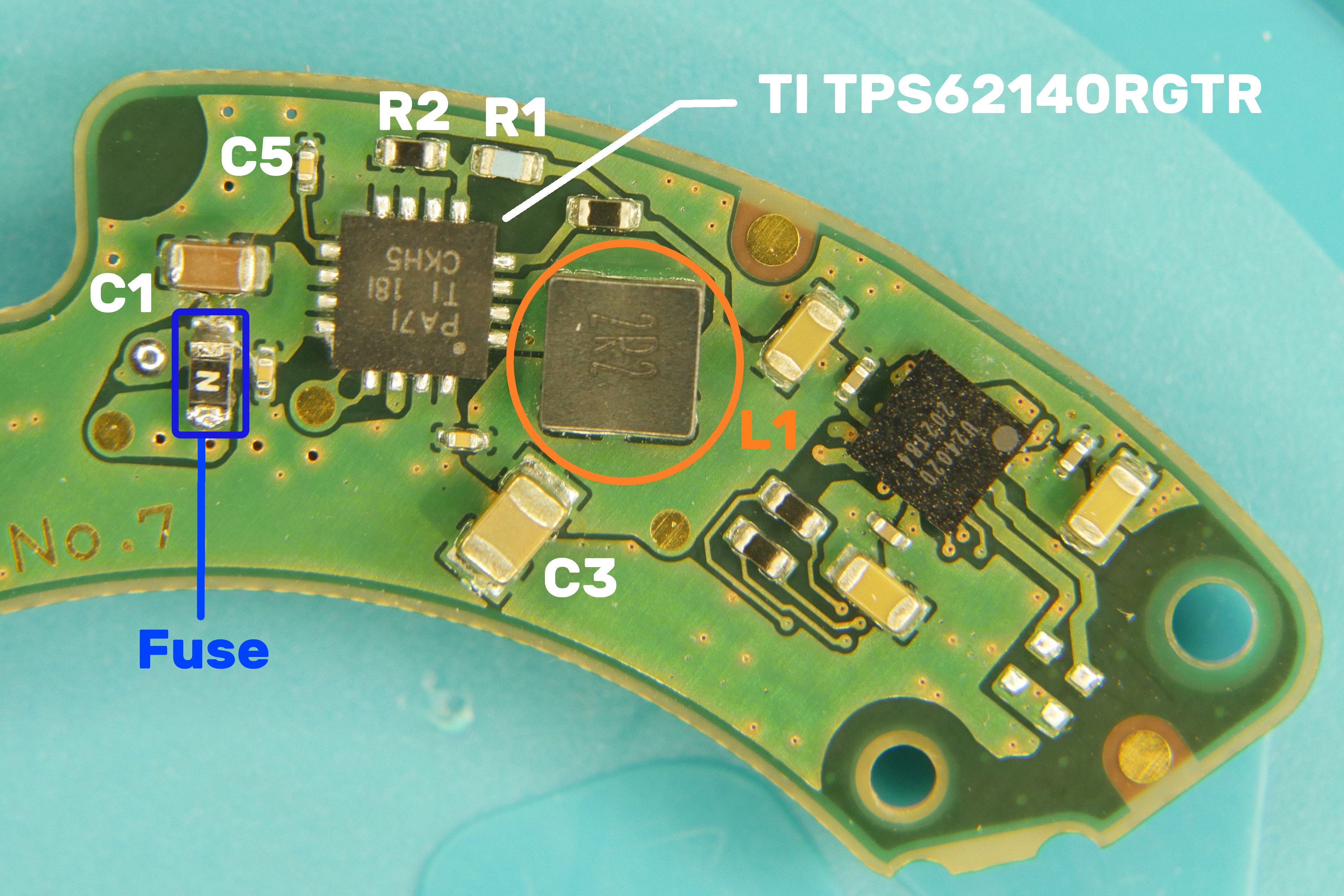
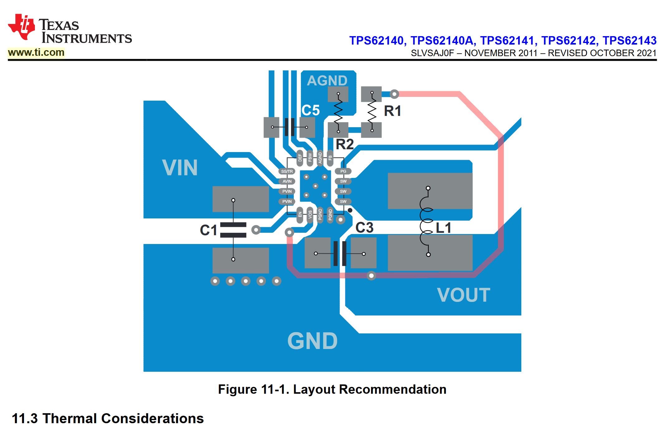
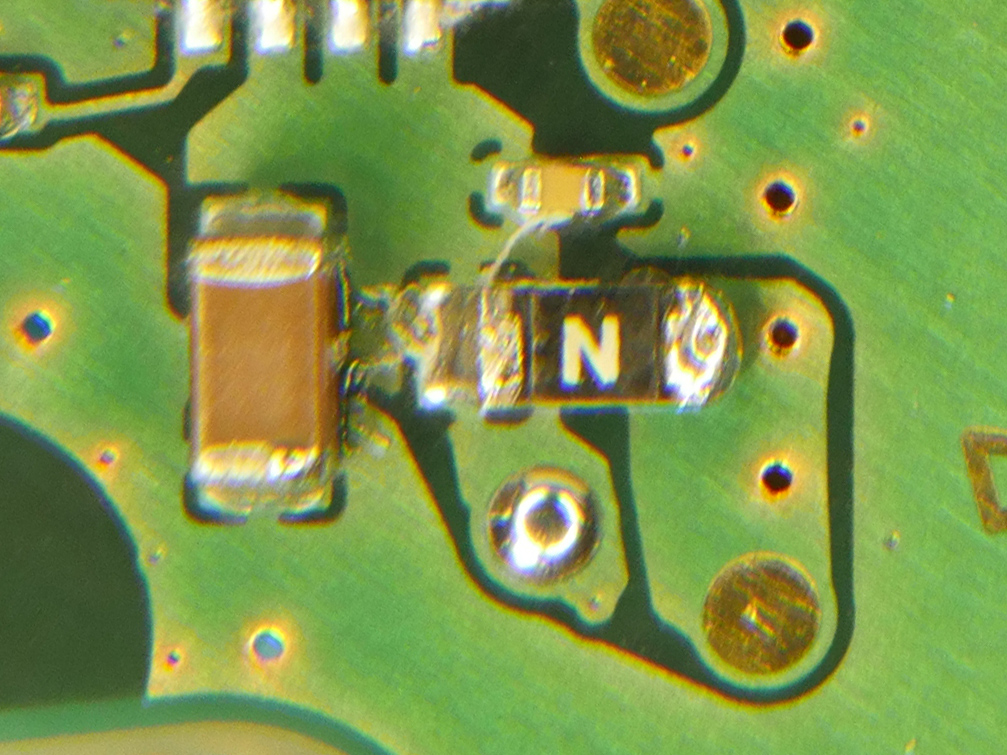
In this case, the 16-VQFN package TI TPS62140RGTR Buck converter, labeled as "PA71 TI 18i" is used in this sigma lens PCB. The layout engineer heeded the advice of the TI datasheet and implemented a very similar layout but added a few components to keep things spicy. Looking over the layout recommendation, "C1" connects Vin to Gnd, and serves as the main input filter capacitor for the dc-dc converter. Inquisitive minds can easily determine that the unknown "N" labeled package adjacent to C1 on the input voltage rail is indeed a fuse to protect the dc-dc from damage. A quick check with the multimeter confirms that the fuse was open, so it took one for the team and saved the DC-DC from destruction.
Searching online for an "N" labeled fuse does not lead to many promising search results but it did bring up a suggested 2a rated smt fuse on aliexpress. The TI TPS62140RGTR datasheet quotes a 2a output current, and while there's operational quiescent current, 2a is likely an appropriate value. Being familiar with the Panasonic Semi smt fuses used all throughout the Lumix camera line, I picked up a 2amp 32v fast blow fuse part# ERB-RE2R00V. The lumix gh3, gh4 and gh5 cameras use a mixture of 32v 2.5a and 1.5a fuses, so I knew I was in the right ballpark. I have found that in camera electronics, 2 terminal resistor-looking packages with arbitrary single letter notation tend to be smt fuses. They sometimes have scalloped terminals.
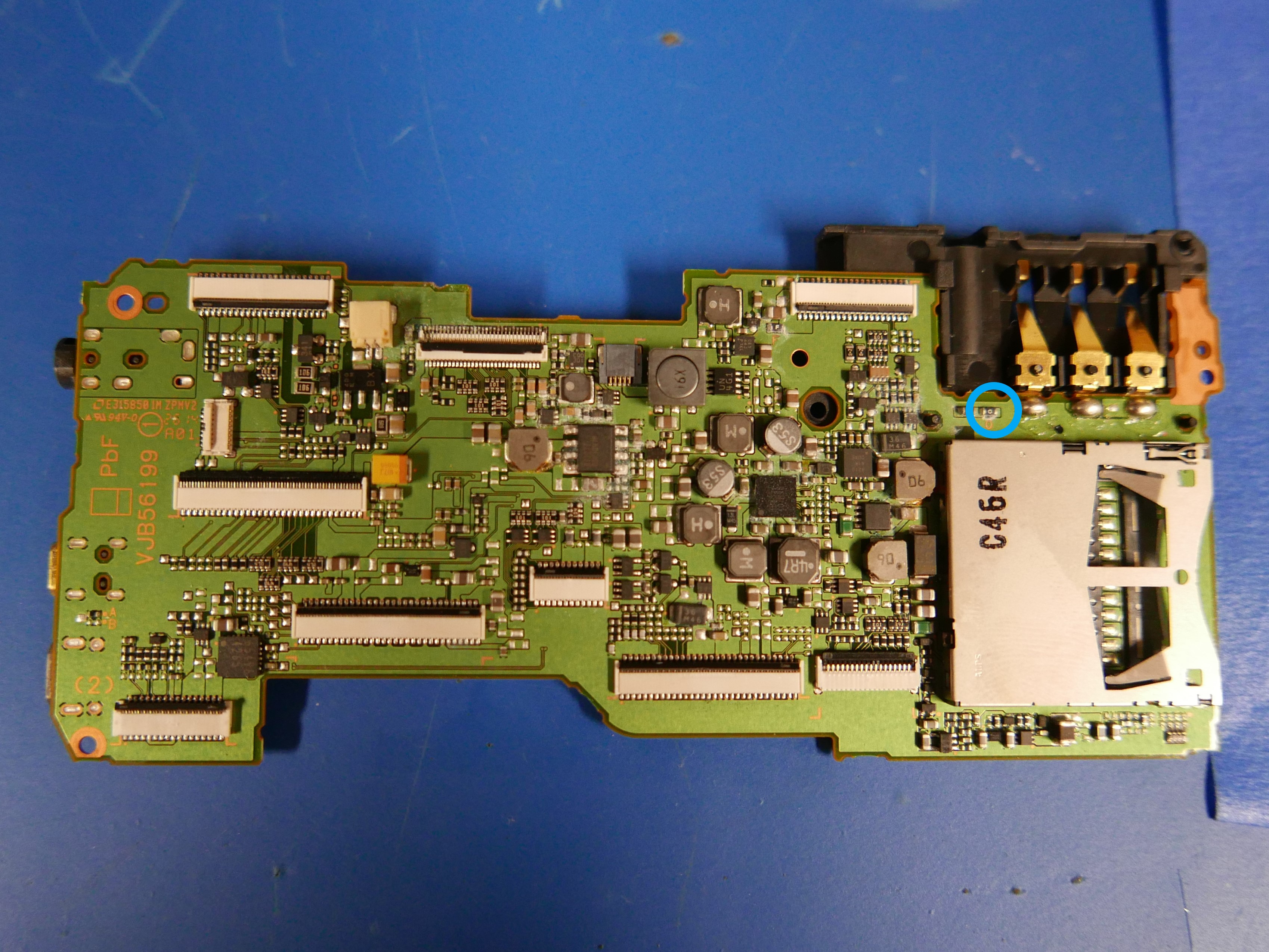
The fuse implemented was sized as 0603, making repair possible with less expensive and precise equipment. 0402 and even 0201 fuses very much exist. The layout engineer also left space beside the fuse for ease of access with repair tools. There have been many times when a fuse was put in a pocket or crowded section of a PCB requiring a nearby component desoldering to gain access to the failed component. An example is the Lumix GH3 / GH4 mainboard that features the battery input fuse sandwiched between an SD card slot and a protruding battery connector. SMT tweezers make this repair a breeze, but wielding two soldering irons also works in a pinch. Desolder the failed fuse, clean the pads, position the new fuse, hold down the fuse and solder one terminal at a time.
As to why the fuse failed, I have not discovered a specific failure point. Certain conclusions can be arrived at, such as specific edge cases where someone leaves the lens in AFC mode (auto focus continuous) and sets the camera to hunt for focus for hours / days on end. It's possible the lens was never designed to be used 24/7 for racking focus and caused the buck converter to pull more current than than 2a fuse could sustain, causing it to open.
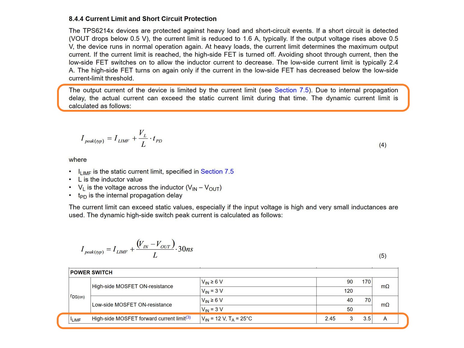
An interesting operational condition in the TI datasheet may provide clues to the failure point. On page 11 it states: "The output current of the device is limited by the current limit (see Section 7.5). Due to internal propagation delay, the actual current can exceed the static current limit during that time." "ILIMF is the static current limit. ILIMF = High-side MOSFET forward current limit. Test conditions: VIN = 12 V, TA = 25°C. Min:2.45A Typ:3A Max:3.5A." Thus in over current situations, due to internal propagation delay, the actual current consumed can exceed the static current limit for a very short amount of time. If the lens control PCB designers implemented a 2a fast-acting smt fuse as estimated, the dc-dc controller would have been operating outside the 2a fuse specification. This is speculation at this point, but failure point analysis is certainly interesting.
What's the TLDR? Does she chooch? Most certainly! This is the lens in action. AFC performance is not lightning fast, but I don't expect it to be! The manual focus dial works wonders and has just the right amount of dampening to make it enjoyable to use. The aperture ring feels like a close cousin to the Lumix LX100, which is nothing short of excellent.
If the fuse was continuous, the next target for inspection would be the output voltage on the dc-dc. Is the output within operational specifications? Is it below or exceeding the power requirements of the main microcontroller? The main micro on this PCB is labeled as a "341Fy 551486" but it is really a Toshiba TMPM341FYXBG. This is a 32bit Arm M3 micro with plenty of features, I/O peripheral support and motor control communication protocols. A microcontroller chip serves as the main communication hub on the control PCB. Dedicated microcontrollers require accurate clock signals to speak with other micros and peripherals in circuit, thus if you find a dedicated crystal oscillator on a PCB, there's a good chance there's a microcontroller nearby!
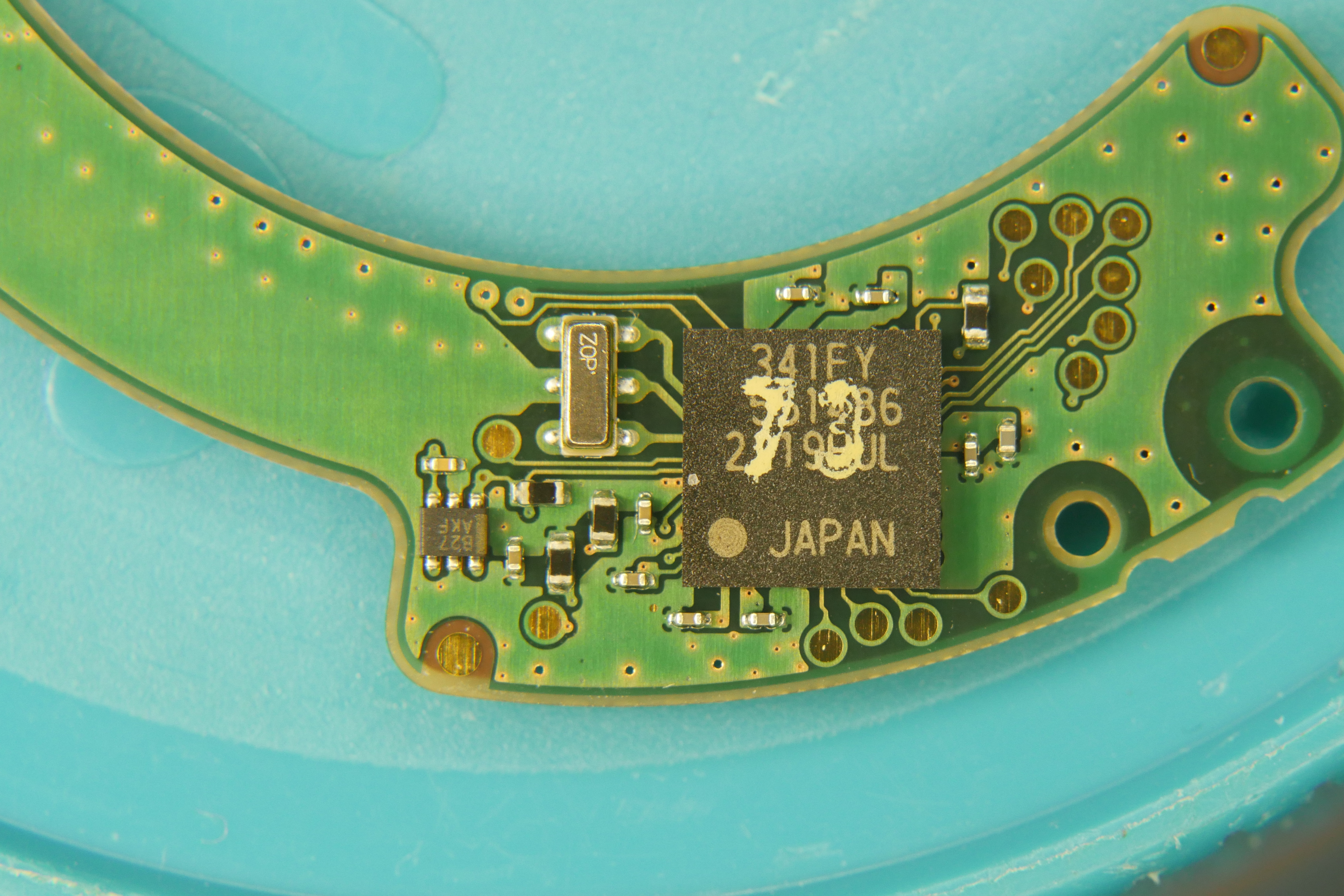
Traditional quartz crystal oscillators vary in operational frequency and are sealed in metal packages silver in luster. They are commonly found in surface mount or through hole packages in many shapes and sizes. MEMS crystal oscillators are a possibility but they are slightly more expensive and thus not as common. MEMS oscillators are usually a very tiny square reflective chip-scale / flip-chip package. Some microcontrollers feature on-chip oscillators but they are not as consistent as external crystals, thus external crystals are still preferred.
Building on previous troubleshooting, the TMPM341FYXBG needs to be checked for input power. Failure of any components between the output rail of the dc-dc controller and the power input of the TMPM341FYXBG can cause the main micro to malfunction. The TMPM341FYXBG is a 0.5mm pitch 6x6mm 113 ball P-TFBGA113 BGA package, meaning there is no easy probing of Vin and gnd. The nearby circuit will have to be investigated. Working with what we know, the main micro is a Arm M3, meaning it's a 3.3v component. The Toshiba datasheet quotes an operational voltage range of 2.7 to 3.6V. If input power to the micro is not within that range, or if there's a short between Vin and ground near the micro, that's definitely a red flag.
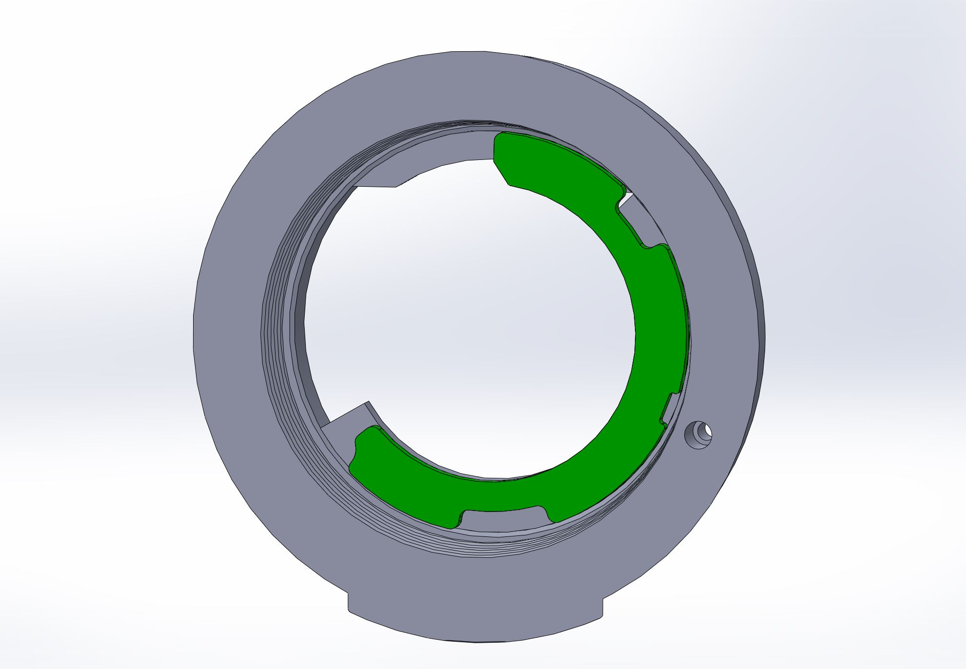
The easiest way to probe for voltages live is to install the lens contact flex back into the control PCB and 3D print a fake lens as a jig in order to get the lens PCB in contact with a camera body on hand. Surprisingly, this is an easier feat than expected since sigma uploaded nearly all of their camera bodies and accessories on grabcad for free. Step files for all y'all. Hats off to sigma for uploading these, most camera companies do not do this. Once the lens control PCB is in position and mounted to the camera, probing can begin. Power traces are conventionally wider than signal traces, so one can go about probing wide traces near the TMPM341FYXBG for 3.3v.
If the microcontroller is receiving power within specification, an additional range of troubleshooting would be necessary to diagnose the lens PCB failure. Luckily, there are circular test pads near the main micro, indicating these control PCBs were programmed and tested on a bed-of-nails jig before assembly. Unfortunately, these test pads are not labeled so finding the correct ones becomes a game of trial and error. A logic analyzer would be needed to probe the test points near the microcontroller. If UART can be discovered on any of the test pins, the logic analyzer can help provide input on whether the microcontroller is booting correctly by deciphering the boot-up bit sequence.
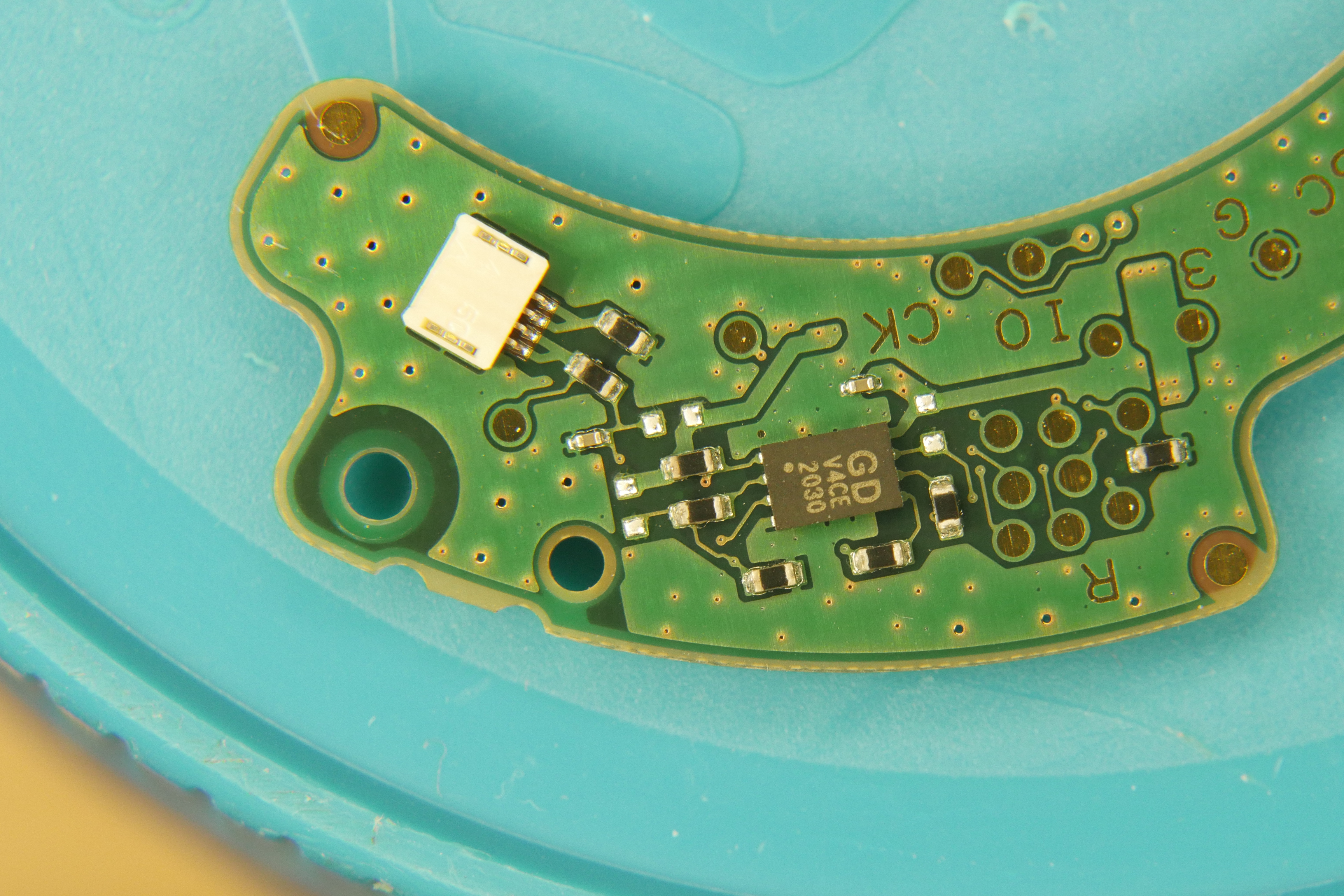
Depending on how far down the rabbit hole you want to go, there is an 8 pin SPI flash package labeled "GD V4CE 2030" which is likely a 8-32mbit nor package that is commonly used with ARM microcontrollers to extend program memory space. While I do not have the exact datasheet for this package, I was able to determine it was indeed flash because "GD" is the designated company prefix for "GigaDevice" a known memory package manufacturer and 8 pin packages are a staple in small sized external flash packages. In this case, the package measures a very small 3*2mm XY footprint and closely matches the USON8 LGA8 packages offered in the GigaDevice datasheet (page 29). The flash chip can be desoldered and the contents can be read / cloned onto another flash package if there was an inkling that the flash package might have failed. The analysis of the flash package exceeds the context of this repair, but it is interesting to investigate the extent of failure analysis.
If the main microcontroller seems to be working correctly, there would likely be some input values displayed on the camera LCD when the lens control PCB is installed, such as aperture or focus distance information. The values may be incorrect but some values should be displayed on the camera display from the lens controller micro. Continuing down the line, the next target would be the motor controller IC. In this case, the "U24020 202184" package is a Rohm BU24020GU motor controller configured as an SPI peripheral. SPI is a synchronous form of communication and requires a clock signal between the master controller and slave device.
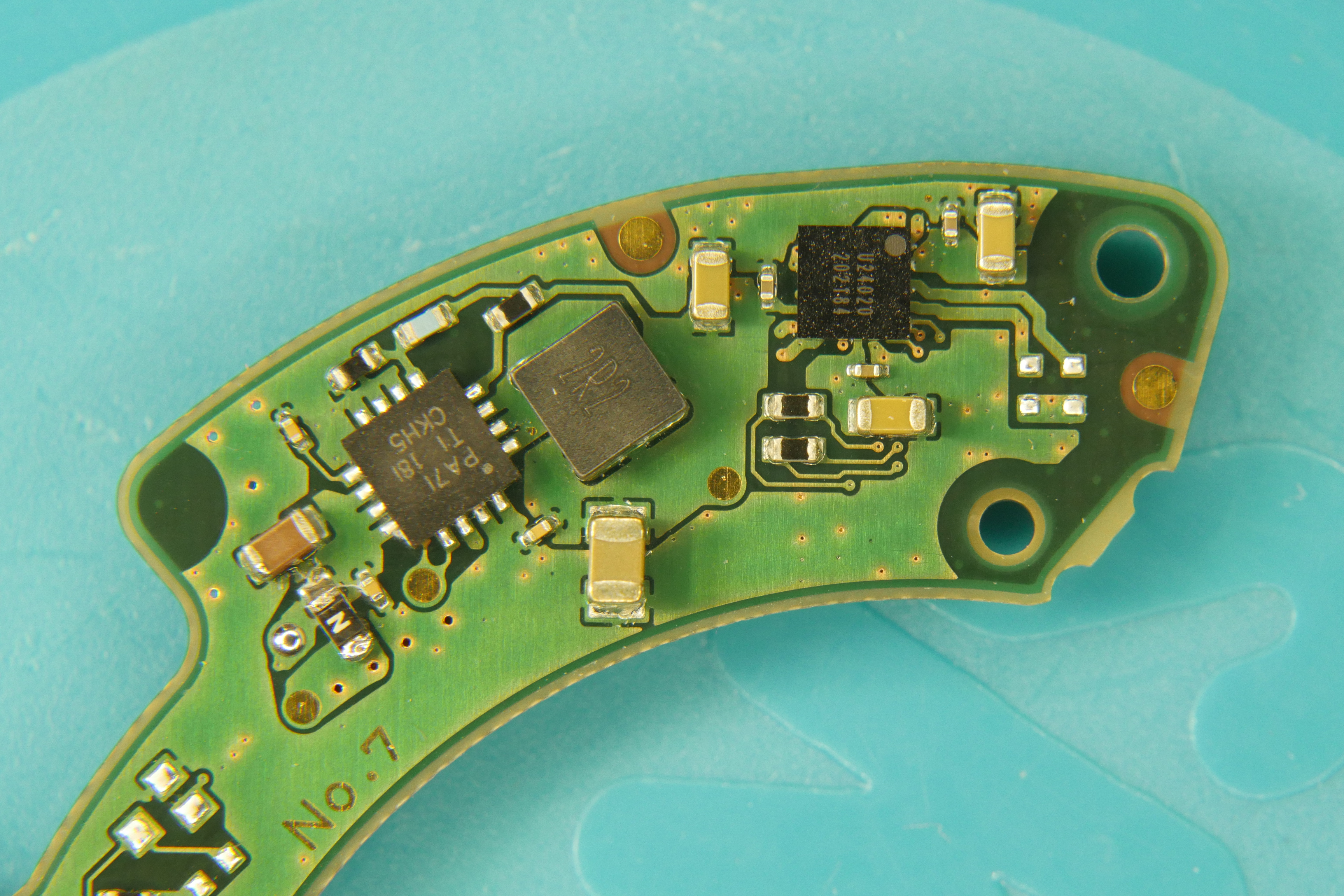
Looking at the PCB macro shot, the BU24020GU has plenty of surrounding passive components but has an unpopulated 4 pin package that was likely intended for a 4 terminal slot-style Photointerrupter but was abandoned later in the development cycle. This is the kind of simplistic sensor that is positioned around a coded rotating disc to log positioning information. Looking over the Rohm datasheet, this is another 3.3v part. Just as before, thou shall check voltages! If the part is not receiving the 2.7 --> 3.6v input range, the chip's not going to work properly. This is unfortunately another BGA component, so probing is going to be challenging. However, physics never left your side, and there's mobile electrons on this here highway. Thicker traces = more electrons!
Looking around the U24020 chip, you can see a pattern in series of three - three arrangements of two capacitors tied to ground. These two capacitors are decoupling capacitors, sized "big" and "small." The big decoupling capacitor is usually between 0.1uf and 1uf while the small capacitor is in the nanofarad range. This arrangement of capacitors is very common and is designed to reduce noise at different frequencies. The datasheet tells us this is a four channel motor controller, and the capacitor arrangement tells us that power to all channels has been laid out on the PCB. Thus, a measurement between any of highlighted power pairs will provide all you need to know. The datasheet lists Vin = DVDD, MVCC12, MVCC34 while Gnd = DVSS, MGND12 MGND34. Vin and gnd are highlighted in the traditional color scheme, red for Vin, black for gnd.
If the motor controller is receiving 3.3v but the lens focus motor is not moving when a focus pull is triggered, make sure to optically inspect the lens focus flex cable. Flex cables tend to fatigue and break if the flex radius is compressed too small. Fatiguing cables can be problematic because depending on the movement of the cable, the focus mechanism can begin to temporarily work again, but it's a false positive as the next flex may kill lens communication.
Looking over the lens PCB macro shots, there are a slew of tiny holes scattered throughout the board. These tiny holes are through hole vias and a large number of them are drilled into the green top layer ground pour. These vias serve as return paths for noisy components on the PCB and connect the outer layer ground pour to inner ground layers. You may have wondered why there are such large clusters of vias in certain parts of the board but not in others. Clusters of vias, or via stitching, is used to provide a low-impedance path for the return current induced by a particularly noisy component. By surrounding a noisy component or region of the PCB, stitching vias can block propagation of electromagnetic waves up to some maximum frequency. The stitching vias implemented here do not fully enclose any trace or specific component, so they do not work as a Faraday cage or as a guard ring, but they do provide noise return paths to help lower radiated EMI during the final design process.
I completed this repair about 2 months ago, just in time for spring's first blooms in the north eastern United States. The 45mm lens has been working a treat in and around the garden and for documenting other electronics projects. I added some sample photos in the behind-the-scenes photoset to show this lens in action. It's amazing that a tiny 0603 component can keep a good lens down and I'm glad I was able to thoroughly document the repair process for others to learn from. All in all, the complete lens teardown and fuse swap took less than an hour! In comparison, this writeup easily exceeded an order of magnitude more time to complete than the repair. Would I do it all again? Most certainly!
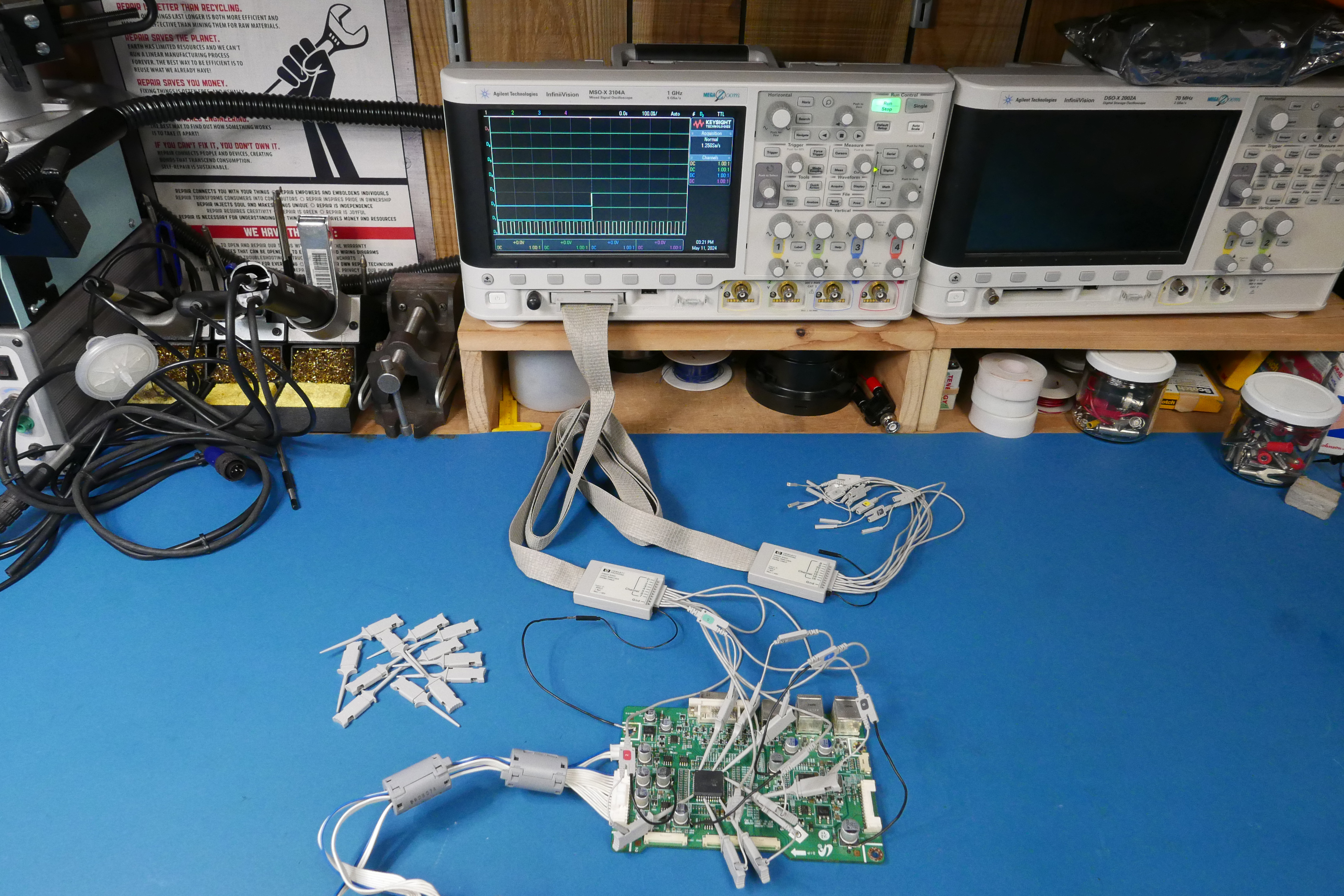
Want more? Here's a behind the scenes look at my workspace and some of the images that did not make the cut to be included in the write-up:
此内容由惯性聚合(RSS阅读器)自动聚合整理,仅供阅读参考。 原文来自 — 版权归原作者所有。