



Container Runtime runs on every node in a Kubernetes (k8s) cluster and is responsible for the entire container lifecycle. Docker is currently the most widely used. With the development of container cloud, more and more container runtimes have emerged. To solve the integration problems between these container runtimes and Kubernetes, the community introduced CRI (Container Runtime Interface) in Kubernetes version 1.5 to support more container runtimes.
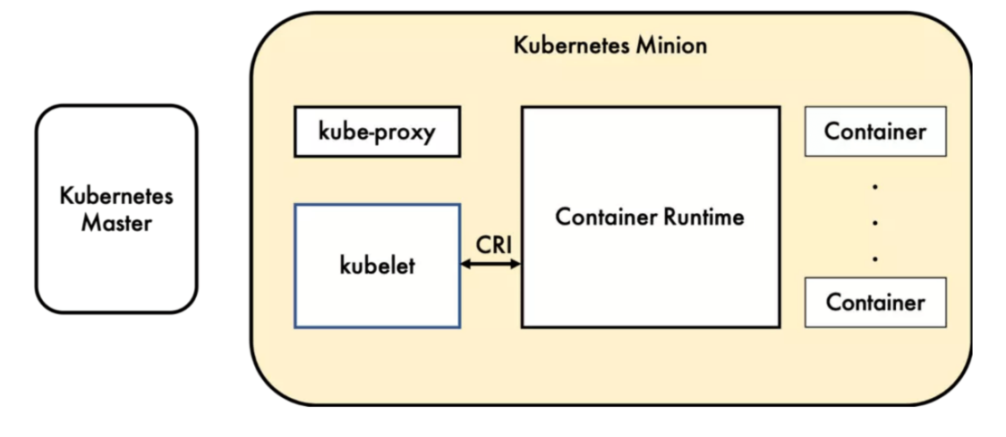
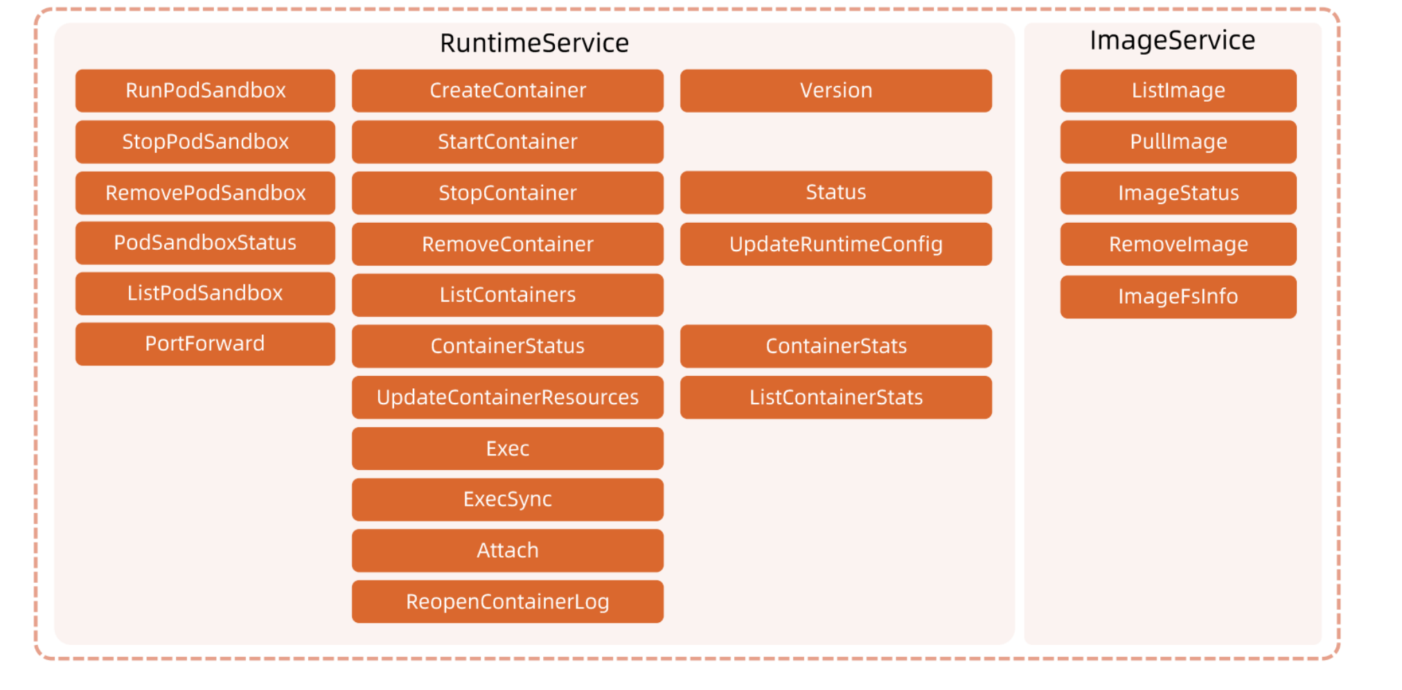
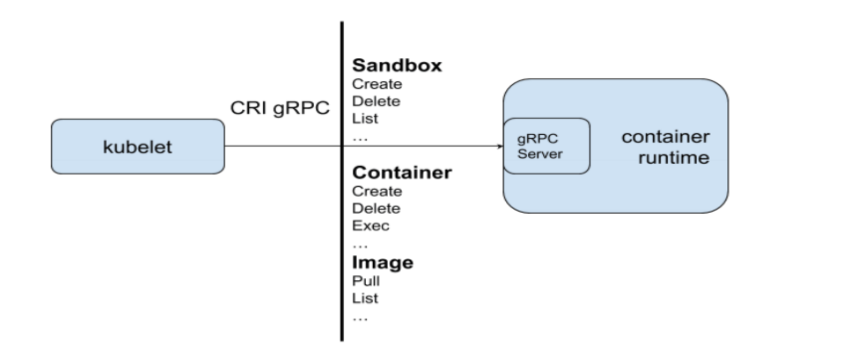
CRI is a set of gRPC services defined by Kubernetes.
kubelet acts as a client, communicating with container runtimes through Socket based on the gRPC framework. It includes two types of services:
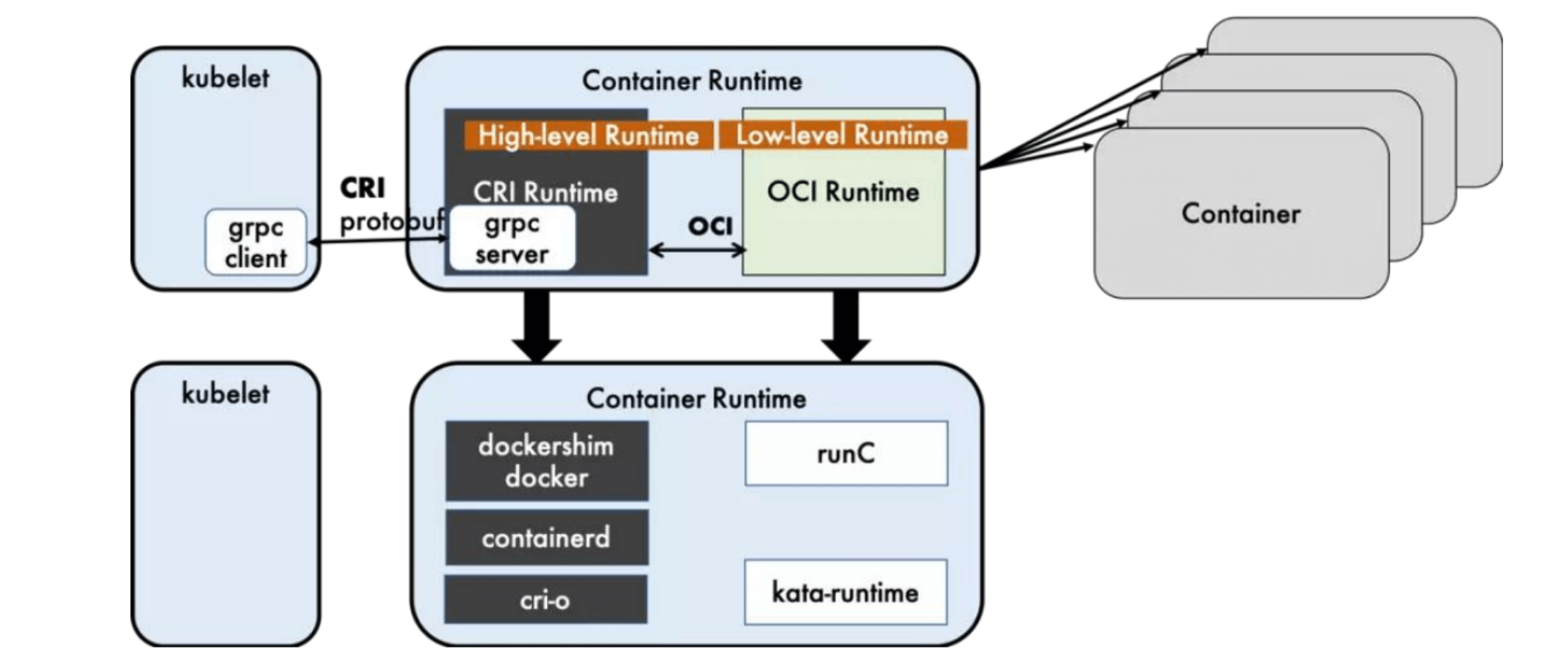
Container runtimes can be divided into high-level and low-level runtimes:
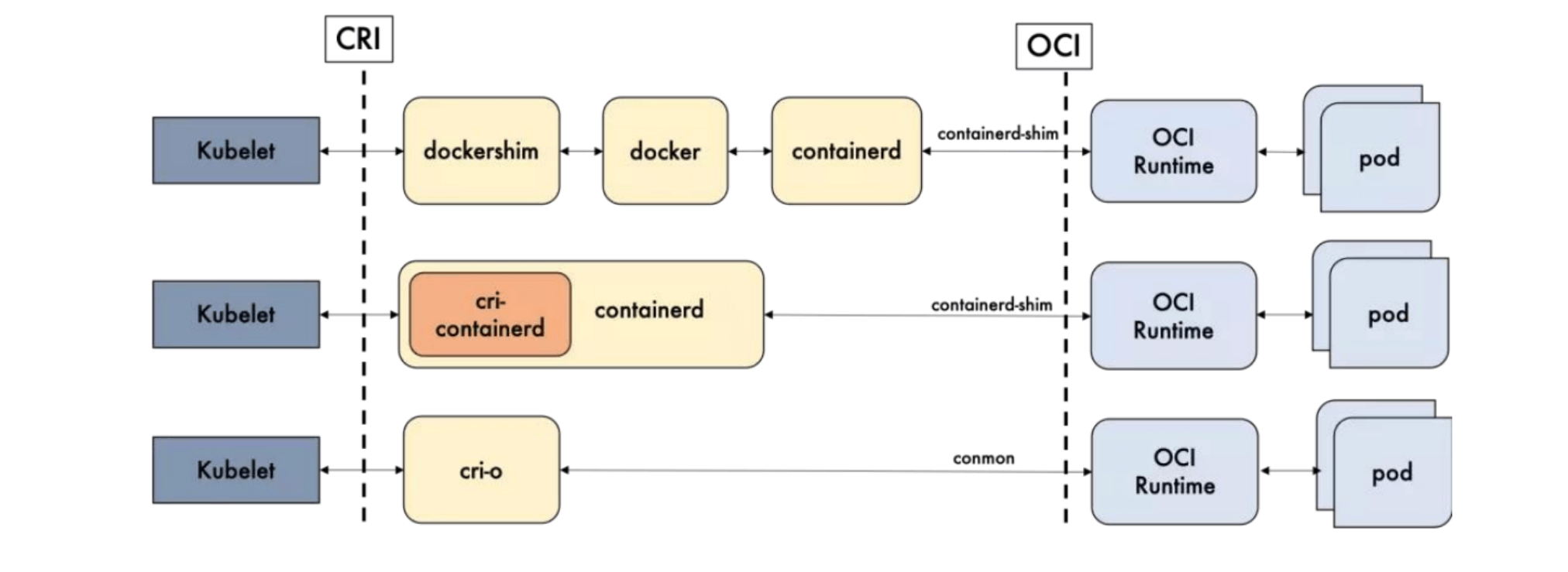
Dockershim, containerd, and CRI-O are all container runtimes that follow CRI, which we call high-level runtimes.
OCI defines the open source industry standards for creating container formats and runtime, including Image Specification and runtime specification.
Image Specification defines the OCI image standard. High-level runtimes will download an OCI image and extract it into an OCI runtime file system bundle.
Runtime Specification describes how to run container programs from OCI runtime file system bundle and defines its configuration, runtime environment, and lifecycle. Operations such as setting namespaces and control groups (cgroups) for new containers and mounting root file systems (rootfs) are all defined here. Its reference implementation is runc, which we call Low-level Runtime.
Low-level runtimes kata and gVisor are still in small-scale deployment or experimental stages, with relatively lacking ecosystem maturity and use cases. So unless there are special requirements, runc is almost the inevitable choice. Therefore, when choosing container runtimes, the focus is mainly on the selection of high-level runtimes.
You might still not understand. Simply put, one side connects to Kubernetes, the other side connects to container processes. The former is high-level runtime, the latter is low-level runtime.
OCI (Open Container Initiative) defines the open source industry standards for creating container formats and runtime, including:
Docker’s multi-layer encapsulation and calls lead to slightly inferior maintainability, increasing the difficulty of troubleshooting online problems. Almost except for restarting Docker, we have no other options. The solutions of containerd and CRI-O are much simpler than Docker.
Docker can be understood as a superset of containerd. If you use docker as runtime, it’s equivalent to starting a heavy dockershim.
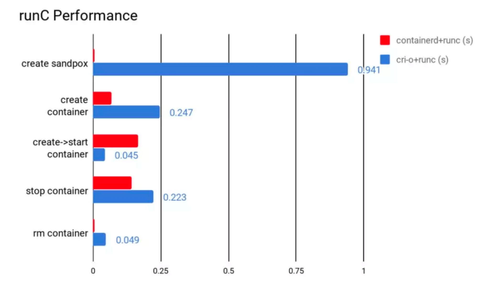
containerd performs well in all aspects except for container startup. From the total time perspective, containerd’s time consumption is still shorter than CRI-O.
So ultimately containerd wins as the optimal solution, though cri-o + runc is also acceptable.
In terms of functionality, both containerd and CRI-O comply with CRI and OCI standards; in terms of stability, containerd has a slight advantage; in terms of performance, containerd wins.
| containerd | CRI-O | Notes | |
|---|---|---|---|
| Performance | Better | Good | |
| Features | Good | Good | CRI & OCI Compatible |
| Stability | Stable | Unknown |
The core component for container runtime functionality inside Docker is containerd. Later, containerd can also directly interface with kubelet through CRI and be used independently in Kubernetes.
This is quite subtle. containerd also provides CLI tools:
crictl pods # can also read pod information
Compared to Docker, containerd reduces the processing modules Dockerd and Docker-shim required by Docker and optimizes the storage drivers supported by Docker. Therefore, it has performance advantages in container creation, startup, stopping, and deletion, as well as in image pulling. The simplified architecture also brings maintenance convenience.
Of course, Docker also has many features that containerd doesn’t have, such as supporting zfs storage drivers, supporting size and file limits for logs, and in the case of using overlayfs2 as storage driver, it can limit the size of container writable layers through xfs_quota. Despite this, containerd can currently basically meet various container management needs, so more and more systems are using it as runtime.
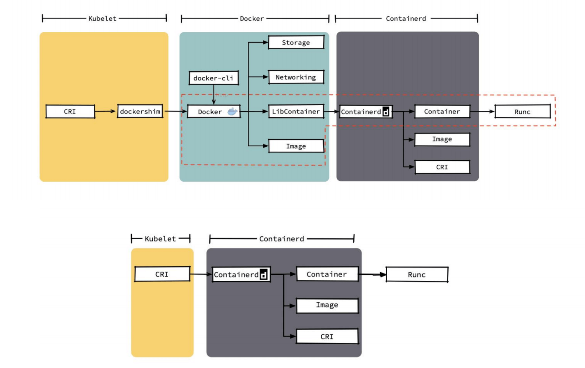
You can see that docker has many features that k8s doesn’t need. k8s only needs the parts in the red box; the rest are redundant. Even if we remove these parts, the remaining call chain is still very long.
In comparison, containerd’s entire code and call chain are far superior to docker’s.
https://kubernetes.io/docs/setup/production-environment/container-runtimes/#containerd
Stop service
systemctl stop kubelet
systemctl stop docker
systemctl stop containerd
Create containerd config folder:
Configure containerd:
sudo mkdir -p /etc/containerd
containerd config default | sudo tee /etc/containerd/config.toml
In containerd, the
sandbox_imageparameter:❯ containerd config default | sudo tee /etc/containerd/config.toml | grep -i "sandbox_image" sandbox_image = "k8s.gcr.io/pause:3.1"Cannot be downloaded in China without VPN.
Update default config
sed -i s#k8s.gcr.io/pause:3.5#registry.aliyuncs.com/google_containers/pause:3.5#g /etc/containerd/config.toml
sed -i s#'SystemdCgroup = false'#'SystemdCgroup = true'#g /etc/containerd/config.toml
Can configure image mirror to Aliyun Cloud
Edit kubelet config and add extra args
vim /etc/systemd/system/kubelet.service.d/10-kubeadm.conf
Environment="KUBELET_EXTRA_ARGS=--container-runtime=remote --container-runtime-endpoint=unix:///run/containerd/containerd.sock --pod-infra-container-image=registry.aliyuncs.com/google_containers/pause:3.5"
Next is to modify Kubernetes startup parameters, telling Kubernetes that my runtime should be changed to containerd.
This location is where kubelet gRPC calls.
Restart
systemctl daemon-reload
systemctl restart containerd
systemctl restart kubelet
Config crictl to set correct endpoint
cat <<EOF | sudo tee /etc/crictl.yaml
runtime-endpoint: unix:///run/containerd/containerd.sock
EOF
OK, I think Kubernetes cluster networking is very complex, and networking itself is very complex. This is true even for engineers with virtual networking and request routing operations experience. Many books (including docker and Kubernetes tutorials) approach network learning as a gradual process. Kubernetes starts from docker networking, docker starts from Linux. We also understood some core networking concepts in the previous docker section, so let’s start from Linux networking.
Linux namespaces contain some fundamental technologies behind most modern container implementations. At a high level, they allow isolation of global system resources between independent processes. For example, PID namespaces isolate the process ID number space. This means that two processes running on the same host can have the same PID!
This level of isolation is obviously useful in the container world. For example, without namespaces, a process running in container A might unmount an important file system in container B, or change the hostname of container C, or delete a network interface from container D. By namespacing these resources, processes in container A don’t even know that processes in containers B, C, and D exist.
The fundamental principles of Kubernetes network model design are:
In Kubernetes clusters, IP addresses are allocated on a per-Pod basis, and each Pod has an independent IP address. All containers within a Pod share a network stack, i.e., a network namespace on the host machine, including their IP addresses, network devices, configurations, etc. This means that all containers in a Pod can connect to each other through localhost:port.
In Kubernetes, a lightweight universal container network interface CNI (Container Network Interface) is provided specifically for setting up and tearing down container network connectivity. Container runtimes complete container network setup by calling network plugins through CNI.
bridge: Create a bridge and insert host and container ports into the bridgeipvlan: Add ipvlan interface for containersloopback: Set up loopback interfaceportmap: Set up host port and container port mappingbandwidth: Use Linux Traffic Control for rate limitingfirewall: Set up firewall rules for containers through iptables or firewalldhttps://github.com/containernetworking/plugins
Container runtimes read JSON format configuration files from CNI’s configuration directory at startup.
cat /etc/cni/net.d # Read this CNI configuration file

ls -al /opt/cni/bin # CNI executable binary files
Files with extensions .conf, .conflist, .json. If the configuration directory contains multiple files, generally, the first configuration file in alphabetical order is selected as the default network configuration, and the specified CNI plugin name and configuration parameters are loaded from it.
We can see there’s a file ending with
.conflist. Yes, k8s CNI allows using multiple plugins simultaneously and passes the execution result of the previous plugin as parameters to the next plugin, so we can chain multiple plugins to let multiple plugins do different things. For example, the first plugin can only be responsible for communication between nodes on the same host, then the second plugin can be responsible for communication between pods on different nodes. In short, as I said, configuration files are available, pod information is also passed by k8s, how you want to play is up to your plugin~
For container network management, container runtimes generally need to configure two parameters --cni-bin-dir and --cni-conf-dir.
cni-bin-dir: Directory where network plugin executable files are located. Default is /opt/cni/bin.cni-conf-dir: Directory where network plugin configuration files are located. Default is /etc/cni/net.d.There’s a special case where kubelet’s built-in Docker as container runtime, kubelet looks for CNI plugins and runs plugins to set up networking for containers. These two parameters should be configured at kubelet.
After k8s v1.24 completely removes docker, this special case won’t need to be considered.
The specific process is as follows:
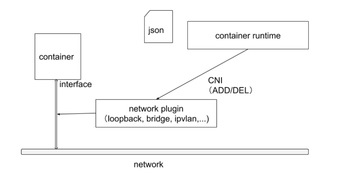
The complete call chain is as follows:
First, Pod is started by kubelet, then kubelet starts Pod through CRI interface.
The process of starting Pod includes network-related configuration, which needs to be implemented by CRI calling CNI.
Therefore, the entire call chain is kubelet --> CRI --> CNI.
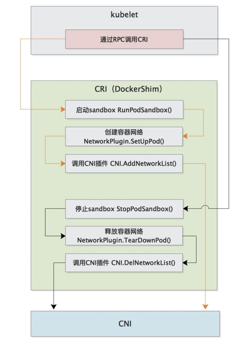
When CNI plugins are deployed, they usually start a DaemonSet and copy binary files from the image to the host’s /opt/cni/bin directory, completing the deployment.
Therefore, writing a CNI plugin actually means providing some binary files with corresponding functionality for kubelet to call.
CNI can set multiple plugins, but CNI is executed in order~
JSON format and can be easily stored in files.ContainerID. Plugins that need to store state should use a primary key composed of network name, container ID, and network interface for indexing.Besides CNI plugins, Kubernetes also requires standard CNI plugin lo with minimum version 0.2.0. Network plugins, besides supporting setting up and cleaning Pod network interfaces, also need to support Iptables. If Kube-proxy works in Iptables mode, network plugins need to ensure container traffic can use Iptables forwarding. For example, if network plugins connect containers to Linux bridge, the net/bridge/bridge-nf-call-iptables sysctl parameter must be set to 1, so packets on the bridge will traverse Iptables rules. If plugins don’t use Linux bridge (but use something like Open vSwitch or other mechanisms), they should ensure container traffic is properly routed.
The ContainerNetworking group maintains some CNI plugins, including bridge, ipvlan, loopback, macvlan, ptp, host-device for network interface creation, DHCP, host-local and static for IP address allocation, and others like Flannel, tuning, portmap, firewall. The community also has some third-party network policy plugins, such as Calico, Cilium, and Weave. The diversity of available options means most users will be able to find CNI plugins suitable for their current needs and deployment environment and quickly switch solutions when circumstances change.
Flannel is a project developed by CoreOS, an early entry-level CNI plugin product that’s simple and easy to use. Flannel uses the existing etcd cluster of Kubernetes cluster to store its state information, eliminating the need for dedicated data storage. It only needs to run the flanneld daemon on each node.
Each node is assigned a subnet for allocating IP addresses to Pods on that node. Pods on the same host can communicate using bridges, while Pods on different hosts will have their traffic encapsulated in UDP packets by flanneld and routed to appropriate destinations. The default and recommended encapsulation method is VxLAN because it has good performance and requires less manual intervention than other options. While encapsulation solutions using technologies like VxLAN work well, the downside is that this process makes traffic tracing difficult.
Meanwhile, Flannel doesn’t support network policy.
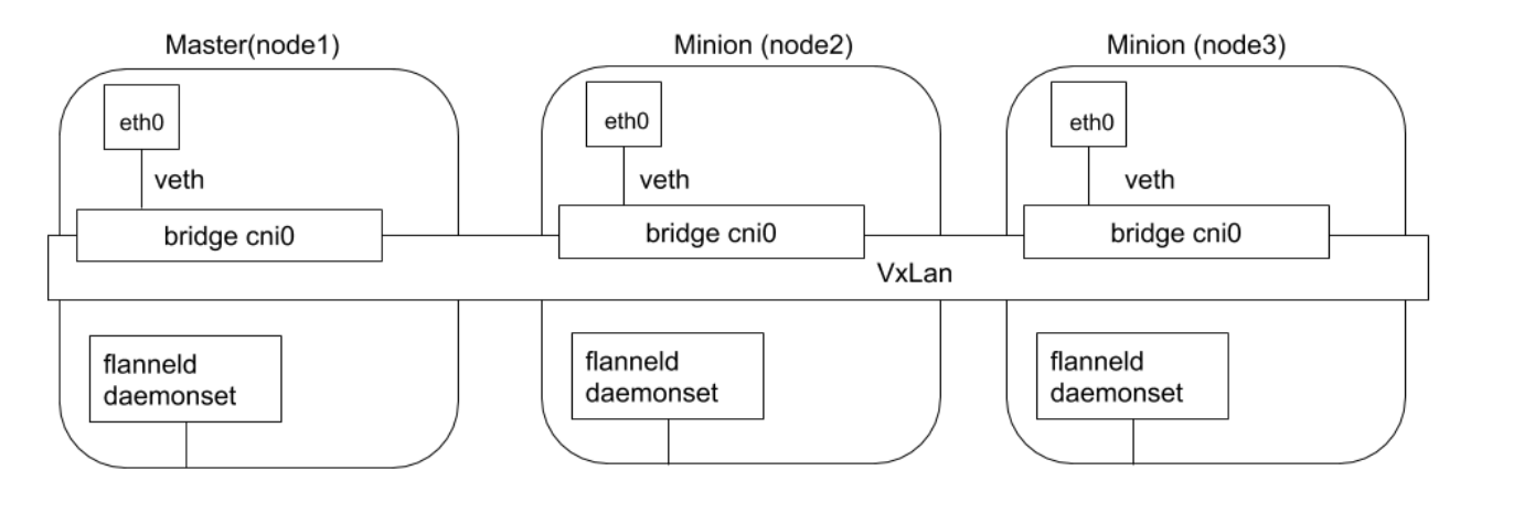
Flannel implements through packet encapsulation and decapsulation.
Calico is known for its performance, flexibility, and network policies, involving not only providing network connectivity between hosts and Pods but also network security and policy management.
For same-segment communication, based on Layer 3, Calico uses BGP routing protocol to route packets between hosts. Using BGP routing protocol also means packets don’t need to be wrapped in additional encapsulation layers when moving between hosts.
For cross-segment communication, based on IPinIP using virtual network device tunl0, one IP packet encapsulates another IP packet. The source address of the outer IP packet header is the IP address of the tunnel entrance device, and the destination address is the IP address of the tunnel exit device.
Network policy is one of Calico’s most popular features, using ACLS protocol and kube-proxy to create iptables filtering rules to achieve container network isolation.
Additionally, Calico can integrate with service mesh Istio to interpret and enforce cluster workload policies at both service mesh layer and network infrastructure layer. This means powerful rules can be configured to describe how Pods should send and receive traffic, improving security and strengthening control over network environments.
Calico belongs to a completely distributed horizontal scaling architecture, allowing developers and administrators to quickly and smoothly scale deployment. For environments with high performance and functionality requirements (like network policies), Calico is a good choice.
Calico has two modes:
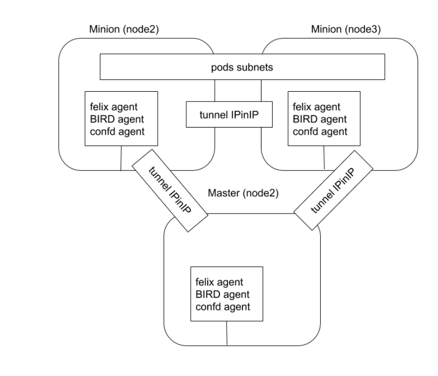
After plugin deployment, it starts DaemonSet, which mounts directories containing configuration files (/etc/cni/net.d) and binary files (/opt/cni/bin) to the Pod, then copies configuration files and binary files from the image to corresponding directories.
DaemonSet runs on all nodes, so it can handle node additions or deletions.
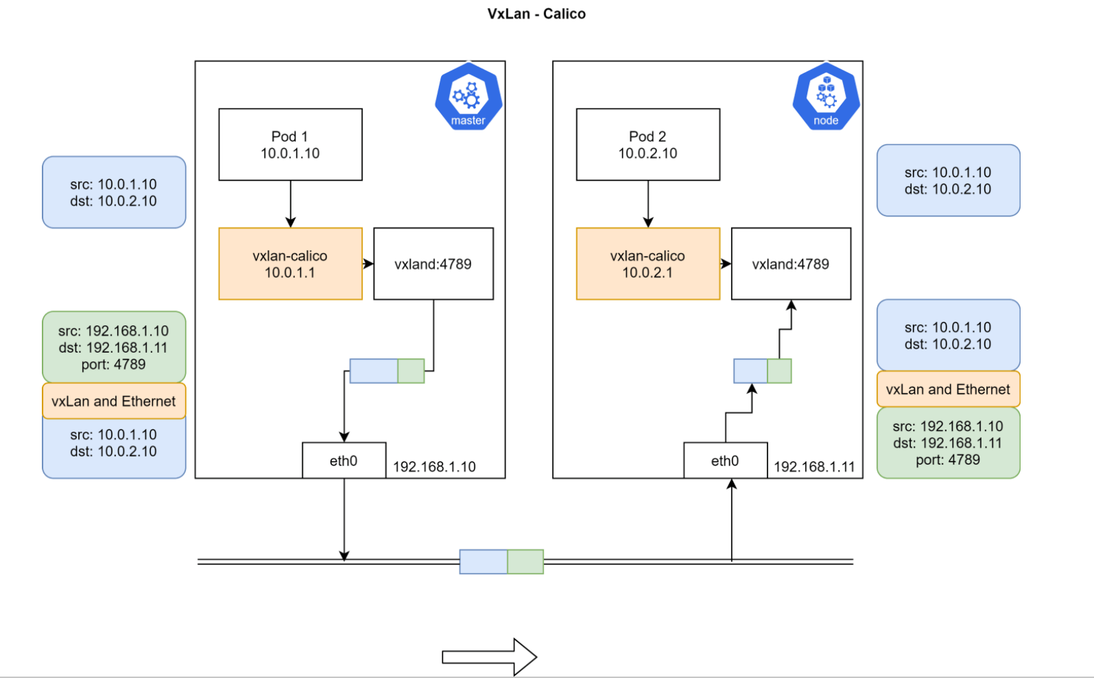
Pod1 and Pod2 are on different Nodes and don’t belong to the same network segment, so they cannot be directly routed.
After installing Calico, there will be a vxland process and vxlan-calico network device on each node. Data from Pod goes through vxlan-calico device to vxland process, which performs packet encapsulation, taking the entire network packet from Pod as payload, then adding IP headers again. The source IP added here is the current node’s IP + vxland listening port 4789, and the destination IP is the IP of the Node where Pod2 is located. Then this packet goes through external node routing from master node to node, then node’s vxland performs packet decapsulation and enters Pod2 through vxlan-calico device.
Actually the principle is the same as Flannel, both use packet encapsulation/decapsulation
Calico uses CRD creation in clusters for storage by default.
Other storage methods can also be configured
First start a container containing many tools, like centos
kubectl run --image=centos centos
Then enter that Pod
$ k exec -it centos-5fdd4bb694-7cgc8 bash
Check that Pod’s IP and routing information
$ ip a
1: lo: <LOOPBACK,UP,LOWER_UP> mtu 65536 qdisc noqueue state UNKNOWN group default qlen 1000
    link/loopback 00:00:00:00:00:00 brd 00:00:00:00:00:00
    inet 127.0.0.1/8 scope host lo
       valid_lft forever preferred_lft forever
3: eth0@if48: <BROADCAST,MULTICAST,UP,LOWER_UP> mtu 1450 qdisc noqueue state UP group default
    link/ether 16:4c:ec:e4:3a:d6 brd ff:ff:ff:ff:ff:ff link-netnsid 0
    inet 192.168.119.78/32 brd 192.168.119.78 scope global eth0
       valid_lft forever preferred_lft forever

$ ip r
default via 169.254.1.1 dev eth0
169.254.1.1 dev eth0 scope link
You can see there’s a default route where all data must be sent to 169.254.1.1 through eth0.
Then use arpping to see which device 169.254.1.1 IP corresponds to
$ arping 169.254.1.1
ARPING 169.254.1.1 from 192.168.119.78 eth0
Unicast reply from 169.254.1.1 [EE:EE:EE:EE:EE:EE]  0.579ms
Unicast reply from 169.254.1.1 [EE:EE:EE:EE:EE:EE]  0.536ms
Found this IP corresponds to MAC address EE:EE:EE:EE:EE:EE.
Then exit container and check on host if there are devices with all-e MAC addresses
$ ip a
45: calie3f1daf7d15@if3: <BROADCAST,MULTICAST,UP,LOWER_UP> mtu 1450 qdisc noqueue state UP group default
    link/ether ee:ee:ee:ee:ee:ee brd ff:ff:ff:ff:ff:ff link-netnsid 11
    inet6 fe80::ecee:eeff:feee:eeee/64 scope link
       valid_lft forever preferred_lft forever
Found there really are devices starting with cali that all have this MAC address. These are actually veth pairs created by calico, with one end in Pod and one end on host.
Then check routing information on host
[root@agent-1 ~]# ip r
default via 192.168.10.1 dev eth0
169.254.169.254 via 192.168.10.3 dev eth0 proto static
blackhole 172.25.0.128/26 proto 80
172.25.0.131 dev cali1cc9705ed50 scope link
172.25.0.132 dev cali9d0f51d41f9 scope link
172.25.0.133 dev cali4dcdb8d77a9 scope link
172.25.0.134 dev caliac318995356 scope link
Found that traffic for several IPs needs to be forwarded to cali* devices. Actually this traffic goes through veth pairs into other containers, which is why pinging other Pods from within Pod works.
Traffic goes to host, makes a round trip, and enters Pod again.
Specific node and IP information as follows:
ipamblock:
10-233-90-0-24
node1
cidr: 10.233.90.0/24

ipamblock:
10-233-96-0-24
node: node2
cidr: 10.233.96.0/24
After calico deployment, it starts a daemon process called bird, whose function is to synchronize routing information between different nodes.
Pod networks are actually private information with no relation to host networks. Other nodes cannot perceive Pod network segments on current node, so bird tool is needed for synchronization.
The specific information synchronized is the binding relationship between IP segments and host IPs. For example, to access IP segment 10.233.96.0/24, forward to 192.168.34.11; to access IP segment 10.233.90.0/24, forward to 192.168.34.10.
Therefore, node1 will have routing information pointing to node2:
10.233.96.0/24 via 192.168.34.11 dev tunl0 proto bird onlink
Similarly, node2 also has routing information to node1:
10.233.90.0/24 via 192.168.34.10 dev tunl0 proto bird onlink
This way they can communicate with each other.
Specific bird-related information can be viewed through calico daemonset:
$ k get po -n calico-system calico-node-xk4kn -oyaml
    - name: CALICO_NETWORKING_BACKEND
      value: bird
    name: calico-node
    readinessProbe:
      exec:
        command:
        - /bin/calico-node
        - -bird-ready
        - -felix-ready
      failureThreshold: 3
      periodSeconds: 10
      successThreshold: 1
      timeoutSeconds: 5
Check bird process on host
$ ps -ef|grep bird
root        2433    2386  0 10:58 ?        00:00:00 runsv bird
root        2435    2386  0 10:58 ?        00:00:00 runsv bird6
root        2505    2469  0 10:58 ?        00:00:00 svlogd -ttt /var/log/calico/bird6
root        2516    2510  0 10:58 ?        00:00:00 svlogd -ttt /var/log/calico/bird
root        3662    2433  0 10:58 ?        00:00:00 bird -R -s /var/run/calico/bird.ctl -d -c /etc/calico/confd/config/bird.cfg
root        3664    2435  0 10:58 ?        00:00:00 bird6 -R -s /var/run/calico/bird6.ctl -d -c /etc/calico/confd/config/bird6.cfg
root        9167    5788  0 11:05 pts/0    00:00:00 grep --color=auto bird
Enter Pod to check bird configuration file
$ k exec -it calico-node-7hmbt -n calico-system cat /etc/calico/confd/config/bird.cfg

router id 192.168.34.2;

protocol direct {
  debug { states };
  interface -"cali*", -"kube-ipvs*", "*"; # Exclude cali* and kube-ipvs* but
                                          # include everything else.  In
                                          # IPVS-mode, kube-proxy creates a
                                          # kube-ipvs0 interface. We exclude
                                          # kube-ipvs0 because this interface
                                          # gets an address for every in use
                                          # cluster IP. We use static routes
                                          # for when we legitimately want to
                                          # export cluster IPs.
}
Corresponding iptables rules:
iptables-save, masq all traffic to outside
-A cali-nat-outgoing -m comment --comment "cali:flqWnvo8yq4ULQLa" -m set --match-set cali40masq-ipam-pools src -m set ! --match-set cali40all-ipam-pools dst -j MASQUERADE --random-fully
For production, generally consider calico or Cilium. Flannel is no longer maintained.
| Solution | Network Policy Support | IPv6 Support | Network Layer Base | Deployment | CLI |
|---|---|---|---|---|---|
| Calico | Yes | Yes | L3(IPinIP,BGP) | DaemonSet | calicoctl |
| Cilium | Yes | Yes | L3 / L4+L7(filtering) | DaemonSet | cilium |
| Contiv | No | Yes | L2(VxLAN) / L3(BGP) | DaemonSet | None |
| Flannel | No | No | L2(VxLAN) | DaemonSet | None |
| Weave net | Yes | Yes | L2(VxLAN) | DaemonSet | None |
【K8s Concepts】Understanding Container Network Interface CNI and CNI Plugins
【Dry Goods Sharing】Kubernetes Container Network CNI Discussion
K8s Networking: Deep Understanding of CNI
Kubernetes CSI (Container Storage Interface) is a storage interface designed for containerized environments, used to integrate persistent storage systems into Kubernetes clusters. The purpose of this interface is to improve storage system pluggability and portability while simplifying storage system management.
Kubernetes supports implementing support and extension for different storage through plugins, based on three approaches:
Among these, CSI is a standardized storage interface that allows Kubernetes to interact with various storage backends. CSI improves storage system pluggability and portability and simplifies storage system management. By understanding how CSI works and how to use it, you can better utilize storage functionality provided by Kubernetes.
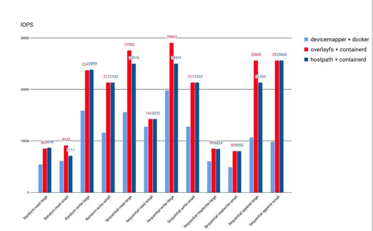
OverlayFS as runtime storage driver;Note this is runtime storage, a file system used for pulling runtime only. It’s not recommended to write anything or logs, as this will affect efficiency.
Kubernetes supports implementing support and extension for different storage through plugins, based on three approaches:
in-tree plugins: Directly download plugins from k8s repository. Currently, k8s community no longer accepts new in-tree storage plugins; they must be supported as out-of-tree plugins
out-of-tree FlexVolume plugins: This mode is also gradually being phased out
FlexVolume means Kubernetes interacts with storage plugins by calling local executable files on compute nodesFlexVolume plugins require host root privileges to install plugin driversFlexVolume storage drivers require hosts to install tools like attach and mount, also needing root access permissions.out-of-tree CSI plugins: CSI plugins interact with storage drivers through RPC, currently mainstream plugin format.
Thinking: Can CNI plugins also be changed to this calling method?
Kubernetes CSI is a storage interface specifically designed for containerized environments that allows Kubernetes to interact with various storage backends. CNI plugins (Container Network Interface) are also Kubernetes plugins, but they have different functions and roles from CSI. CNI plugins are used to integrate network plugins into Kubernetes to provide network services for containers, while CSI plugins are used to integrate persistent storage systems into Kubernetes clusters to provide persistent storage services for containers. Although both CNI and CSI plugins are plugin mechanisms, their calling methods and implementation approaches are different, so CNI plugins cannot be changed to CSI plugin calling methods.
CSI drivers are bridges between CSI interfaces and storage backends. They allow Kubernetes to interact with various storage backends (such as local storage, network storage, cloud storage) and can be loaded and unloaded as plugins.
The Kubernetes community has written CSI drivers for some storage backends (such as Ceph, NFS, and AWS EBS) and supports other storage backends in writing their own CSI drivers. These drivers allow Kubernetes to interact with storage backends and expose storage backend functionality to Kubernetes users.
When designing CSI, Kubernetes has few requirements for CSI storage driver packaging and deployment, mainly defining two related Kubernetes modules:
Using CSI plugins:
To use CSI, the following steps need to be completed:
CSI drivers generally include modules like external-attacher, external-provisioner, external-resizer, external-snapshotter, node-driver-register, CSI driver, which can be deployed in different ways according to actual storage types and requirements.
| Module | Description |
|---|---|
| external-attacher | Used to attach existing storage volumes to nodes |
| external-provisioner | Used to create new storage volumes on storage backend and attach them to nodes |
| external-resizer | Used to resize storage volumes |
| external-snapshotter | Used to create snapshots for storage volumes and restore them when needed |
| node-driver-register | Used to register CSI drivers to Kubernetes nodes |
| CSI driver | Used to implement CSI interface and interact with storage backend |
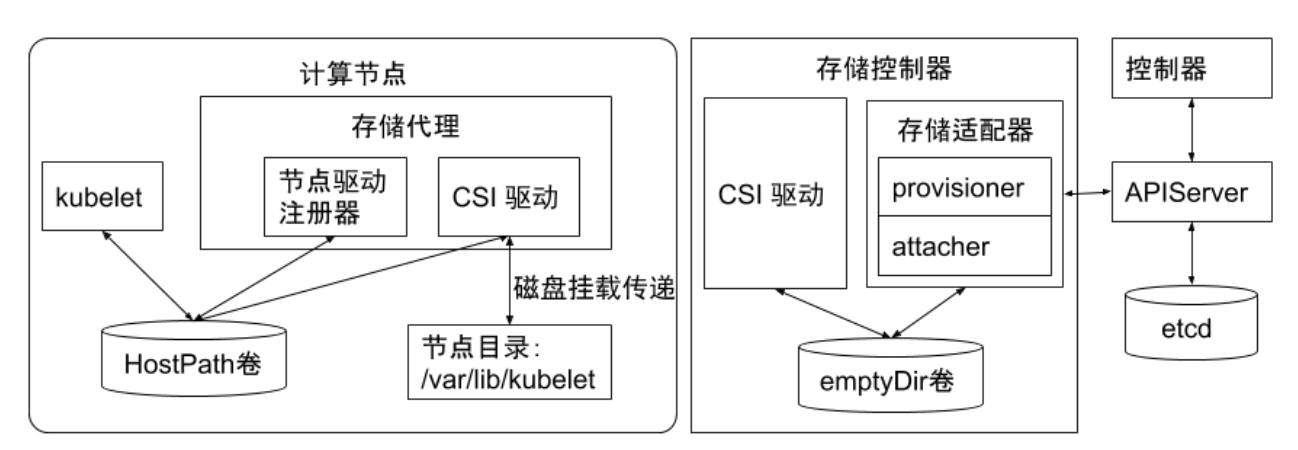
hostPath volume is the simplest and most common volume type in Kubernetes, which can mount directories or files on nodes to containers. hostPath volumes are very suitable for temporary storage, such as log files. However, since hostPath volume lifecycle is closely related to Pod lifecycle, it’s not suitable for persistent storage. If Pod is deleted, data in hostPath volume won’t be cleaned and will remain there.
emptyDir volume is another simple volume type in Kubernetes, which is an empty directory created when Pod is created. emptyDir volumes can be used to share files between containers and also for storing temporary data like log files. Unlike hostPath volumes, emptyDir volume lifecycle is the same as Pod lifecycle. When Pod is deleted, data in emptyDir volume is also deleted.
Besides these three storage volume types, Kubernetes storage functionality can be extended by defining custom storage volumes. Custom storage volumes can be implemented through Kubernetes plugins or external storage systems.
When using storage volumes, one or more volumes need to be defined in Pod’s YAML configuration file, then volumeMounts are used in containers to mount these volumes. This way, containers can access data stored in volumes.
If persistent storage volumes need to be used for data storage, storage classes also need to be set up in Kubernetes clusters. Storage classes are Kubernetes resources used to define storage volume types, which can map PVCs to specific storage volume types and providers.
Common temporary storage is mainly emptyDir volumes.
emptyDir is a volume type frequently used by users. As the name suggests, the “volume” is initially empty. When Pod is removed from node, data in emptyDir volume is also permanently deleted. But when Pod containers exit and restart for some reason, data in emptyDir volume won’t be lost.
By default, emptyDir volumes are stored on storage media supporting that node, which can be local disk or network storage. emptyDir can also notify Kubernetes to mount tmpfs for containers by setting emptyDir.medium field to “Memory”, where data is stored in memory, much faster than local and network storage. But during node restart, memory data is cleared; if stored on disk, data remains after restart. Additionally, memory used by tmpfs is counted in container’s total memory usage, subject to system Cgroup limits.
emptyDir is initially designed to serve applications as cache space or store intermediate data for quick recovery. However, this doesn’t mean all users meeting above requirements are recommended to use emptyDir. We need to judge whether to use emptyDir based on actual business characteristics. Because emptyDir space is located on system root disk and shared by all containers, Pod eviction operations will be triggered when disk usage is high, thus affecting business stability.
apiVersion: v1
kind: Pod
metadata:
  name: my-pod
spec:
  containers:
  - name: test-container
    image: ubuntu
    volumeMounts:
    - name: my-volume
      mountPath: /data
  volumes:
  - name: my-volume
    emptyDir:
      medium: Memory
Common semi-persistent storage is mainly hostPath volumes. hostPath volumes can mount files or directories from host node file system to specified Pods.
For ordinary users, such volumes are generally not needed, but for many Pods that need to obtain node system information, they are very necessary. For example, hostPath usage examples:
/var/log/pods path./proc directory through hostPath.When using hostPath, besides setting required path attribute, users can optionally specify types for hostPath volumes, supported types include directories, character devices, block devices, etc.
apiVersion: v1
kind: Pod
metadata:
  name: my-pod
spec:
  containers:
  - name: test-container
    image: ubuntu
    volumeMounts:
    - name: my-volume
      mountPath: /data
  volumes:
  - name: my-volume
    emptyDir: {}
Persistent storage support is a necessary feature for all distributed systems.
For persistent storage, Kubernetes introduces concepts of StorageClass, Volume, PVC (Persistent Volume Claim), PV (Persistent Volume) to manage storage independently of Pod lifecycle.
Kubernetes currently supports persistent storage including various mainstream block storage and file storage, such as awsElasticBlockStore, azureDisk, cinder, NFS, cephfs, iscsi, etc., which can be broadly categorized into network storage and local storage.
StorageClass is used to indicate storage types. Different storage types can provide services to users through different StorageClasses.
StorageClass mainly contains storage plugin provisioner, volume creation and mount parameters fields.
Created by users, representing user storage requirement declarations, mainly containing required storage size, storage volume access modes, StorageClass types, etc. Storage volume access modes must be consistent with storage types.
Created in advance by cluster administrators or dynamically created based on PVC application requirements, representing real storage space in system backend, which can be called volume space.
Create a PV in k8s to represent external system storage space.
Users create PVCs to request storage. Controllers create volumes on storage backends and then create PVs through StorageClass and size declarations requested by PVCs. Pods reference storage by specifying PVCs.
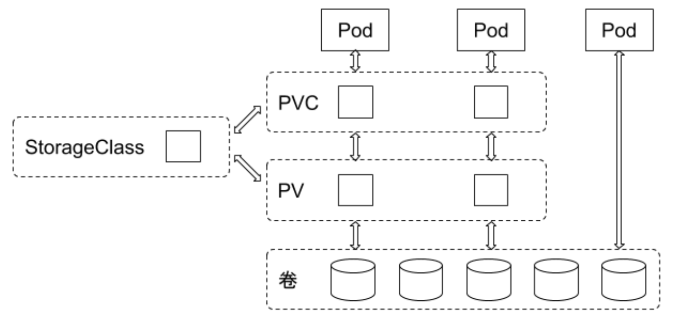
Pod specifies which PVC to use, PVC associates with PV, PV corresponds to backend storage.
Which plugin-controlled backend storage specifically needs to be created is controlled by StorageClass specified in PVC.
apiVersion: v1
kind: Pod
metadata:
  name: my-pod
spec:
  containers:
  - name: test-container
    image: ubuntu
    volumeMounts:
    - name: my-volume
      mountPath: /data
  volumes:
  - name: my-volume
    persistentVolumeClaim:
      claimName: my-pvc
Different media type disks need different StorageClass settings for user differentiation. StorageClass needs to set disk media types for users to understand storage properties.
In local storage PV static deployment mode, each physical disk should create only one PV rather than dividing into multiple partitions to provide multiple local storage PVs, avoiding I/O interference between partitions during use.
Local storage needs to be used with disk detection. When cluster deployment scales up, local storage PVs in each cluster may exceed tens of thousands. Disk damage will be frequent events. At this time, specific processing is needed for node disks and corresponding local storage PVs when disk damage and disk loss are detected, such as triggering alarms, automatic node cordoning, automatic user notification, etc.
For disk management of nodes providing local storage, flexible management and automation are needed. Node disk information can be unified and centrally managed. Add deployment logic in local-volume-provisioner. When containers start, pull disk information that nodes need to provide local storage, such as disk device paths, providing local storage in Filesystem or Block mode, or whether to join certain LVM virtual groups (VG), etc. local-volume-provisioner formats disks or joins certain VGs based on obtained disk information, forming automated closed loop for local storage support.
Recommendations:
Besides the three storage volume types supported by Kubernetes, LocalVolume can also be used to create exclusive local storage volumes. LocalVolume is a storage type in Kubernetes that associates Pods with directories or devices on local disks to provide exclusive storage space. LocalVolume is suitable for applications requiring local disk access, such as databases or file servers.
Here’s an example YAML configuration using LocalVolume:
apiVersion: v1
kind: Pod
metadata:
  name: my-pod
spec:
  containers:
  - name: test-container
    image: ubuntu
    volumeMounts:
    - name: my-volume
      mountPath: /data
  volumes:
  - name: my-volume
    local:
      path: /mnt/disks/data
In the above example, we associate Pod with local disk directory at path /mnt/disks/data to provide exclusive storage space. We use local type to specify volume type and specify path as path field value.
Unlike other storage volume types, LocalVolume cannot be shared by multiple Pods. This is because file systems and data on local disks can only be accessed by one Pod. If data sharing between multiple Pods is needed, other storage volume types should be used, such as NFS or iSCSI.
local-volume-provisioner DaemonSet.resources.request.storage and volumeMode, and selects appropriate node for Pod.pv.Spec.claimRef to corresponding PVC and sets annotation pv.kubernetes.io/bound-by-controller value to “yes”.pv_controller synchronizes PVC and PV status and binds PVC and PV.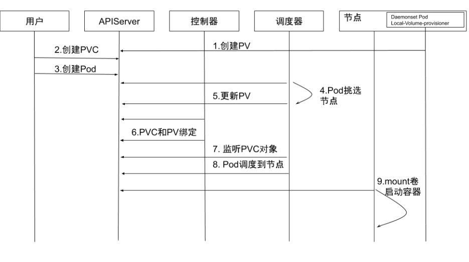
Dynamic Local Volume is a storage volume type in Kubernetes that can dynamically create and delete local storage volumes to provide exclusive storage space. Unlike other storage volume types, Dynamic Local Volume doesn’t require manually creating local storage volumes in advance but dynamically creates local storage volumes when Pods are created. This makes using local storage volumes in Kubernetes clusters more flexible and convenient.
Dynamic Local Volume can be implemented through Kubernetes plugins or local storage systems. Before using Dynamic Local Volume, LocalVolumeDiscovery plugin needs to be set up in Kubernetes cluster first. LocalVolumeDiscovery plugin is used to automatically discover and create local storage volumes for association with Pods.
CSI drivers need to report storage resource information on nodes for scheduling use.
But different machine manufacturers have different reporting methods.
For example, some manufacturers’ machine nodes have multiple storage media like NVMe, SSD, HDD and hope to report these storage media separately.
This requirement differs from other storage type CSI driver interface requirements. Therefore, how to report node storage information and how to apply node storage information to scheduling currently has no unified opinion.
Cluster administrators can make some code modifications to open-source CSI drivers and scheduling based on actual node storage conditions, then deploy and use them.
annotation:volume.kubernetes.io/selected-node: <node name>.pv.Spec.claimRef set to corresponding PVC.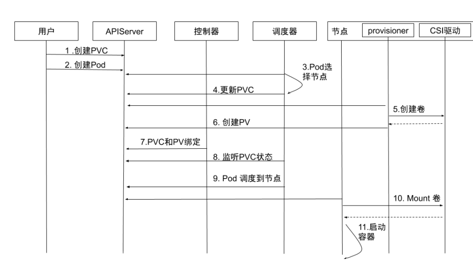
If disk space is used as a storage pool (like LVM) for dynamic allocation, then in the use of allocated logical volume space, there may be I/O interference from other logical volumes because underlying physical volumes might be the same.
If PV backend disk space is an independent physical disk, then I/O won’t be interfered.
Rook is an open-source distributed storage orchestration system for cloud-native environments, currently supporting storage systems like Ceph, NFS, EdgeFS, Cassandra, CockroachDB. It implements an automatically managed, automatically scaling, automatically healing distributed storage service.
Rook supports automatic deployment, startup, configuration, allocation, scaling/shrinking, upgrade, migration, disaster recovery, monitoring, and resource management.
此内容由惯性聚合(RSS阅读器)自动聚合整理,仅供阅读参考。 原文来自 — 版权归原作者所有。
