







作りましょう 作りましょう
あなたと私の世界をさぁ作りましょう
始めましょう 始めましょう
なにから始めましょう(ん~!?)
OK, let's start from communicating between Raspberry Pi 4 and Arduino Micro with hardware UART. For Raspberry Pi, GPIO pin 14 and 15 are the TX and RX pin of UART correspondingly.
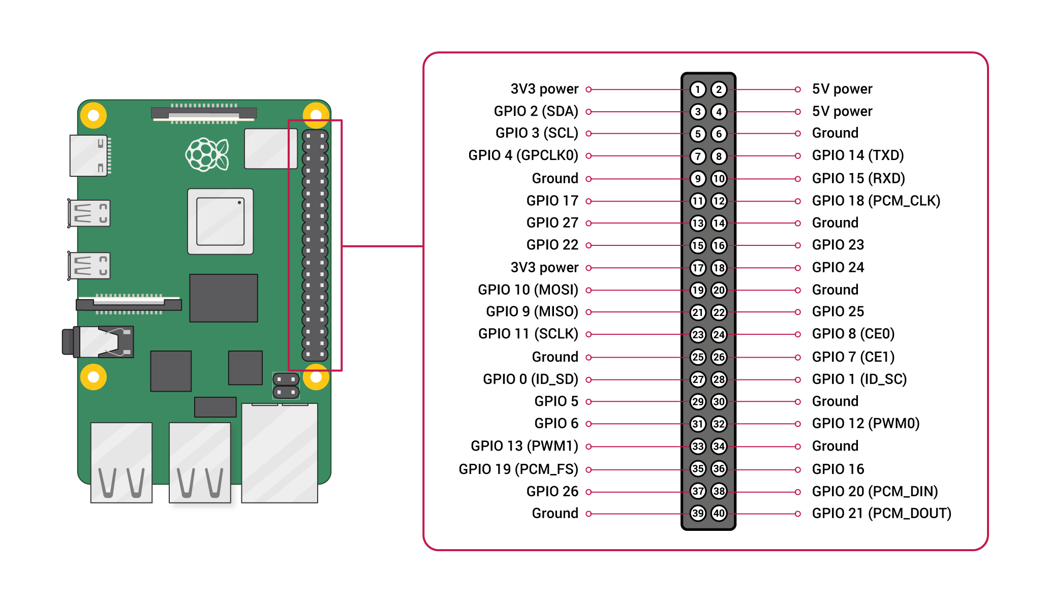
1. Physical Connection
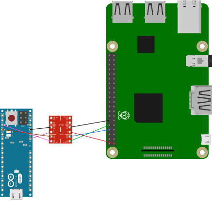
The first thing to note is that all GPIO pins on Raspberry Pi are 3.3v tolerance and Arduino Micro runs at 5v. If we connect Raspberry Pi with Arduino Micro directly, chances are that your Raspberry Pi can be damaged. Thus we need a bi-directional logic level converter.
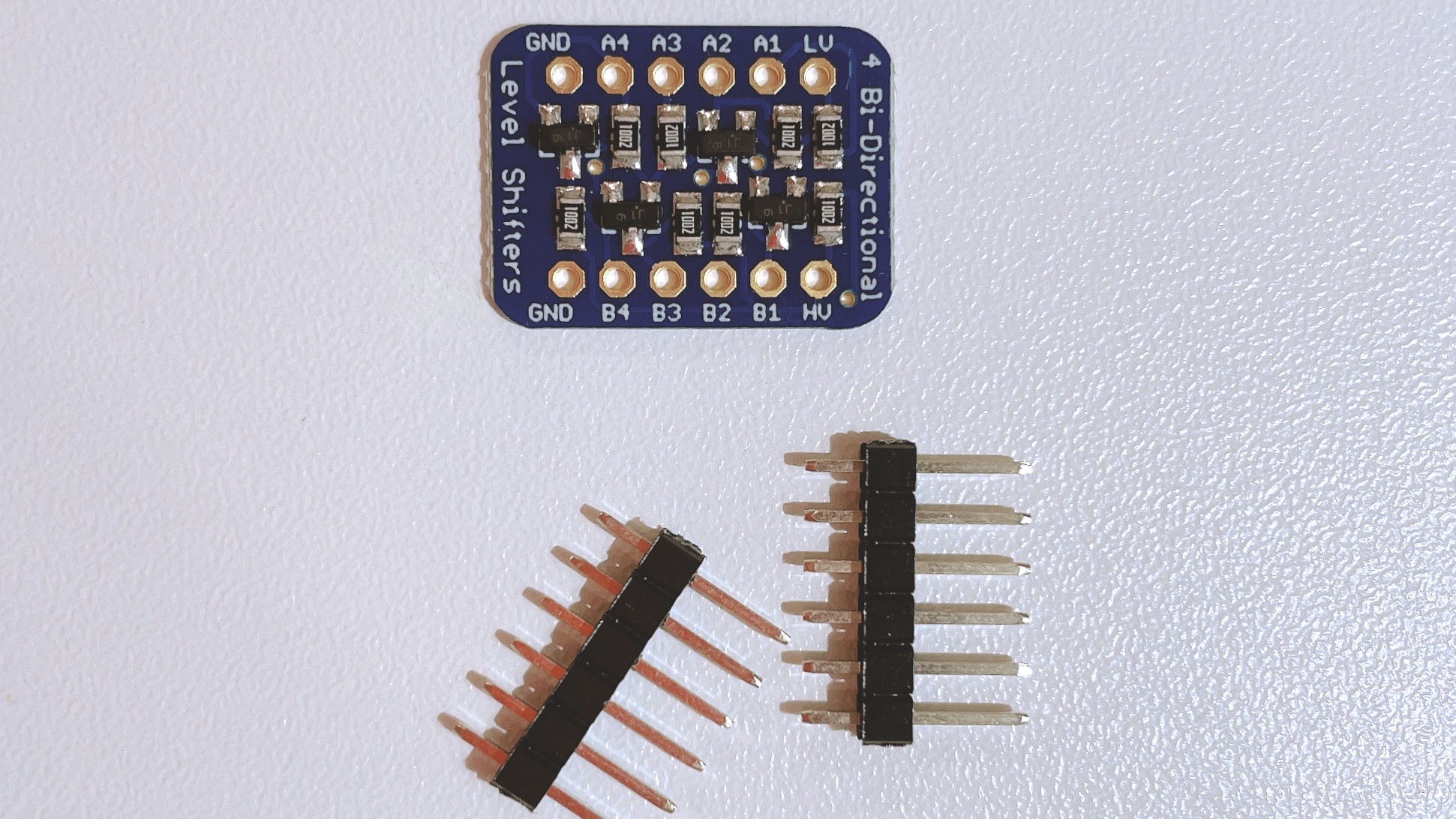
But unfortunately, the one I brought came with separate headers that I needed to solder them onto the converter board by myself.
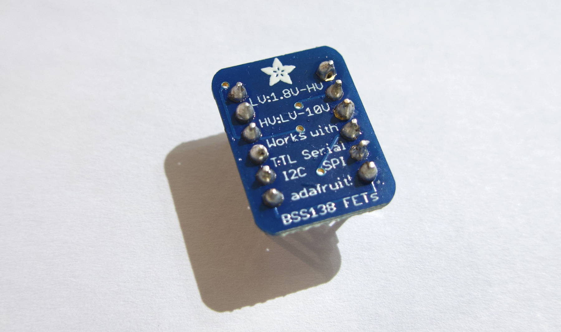
Well, the solder work may look just so so, but it works. That's what matters most. XD
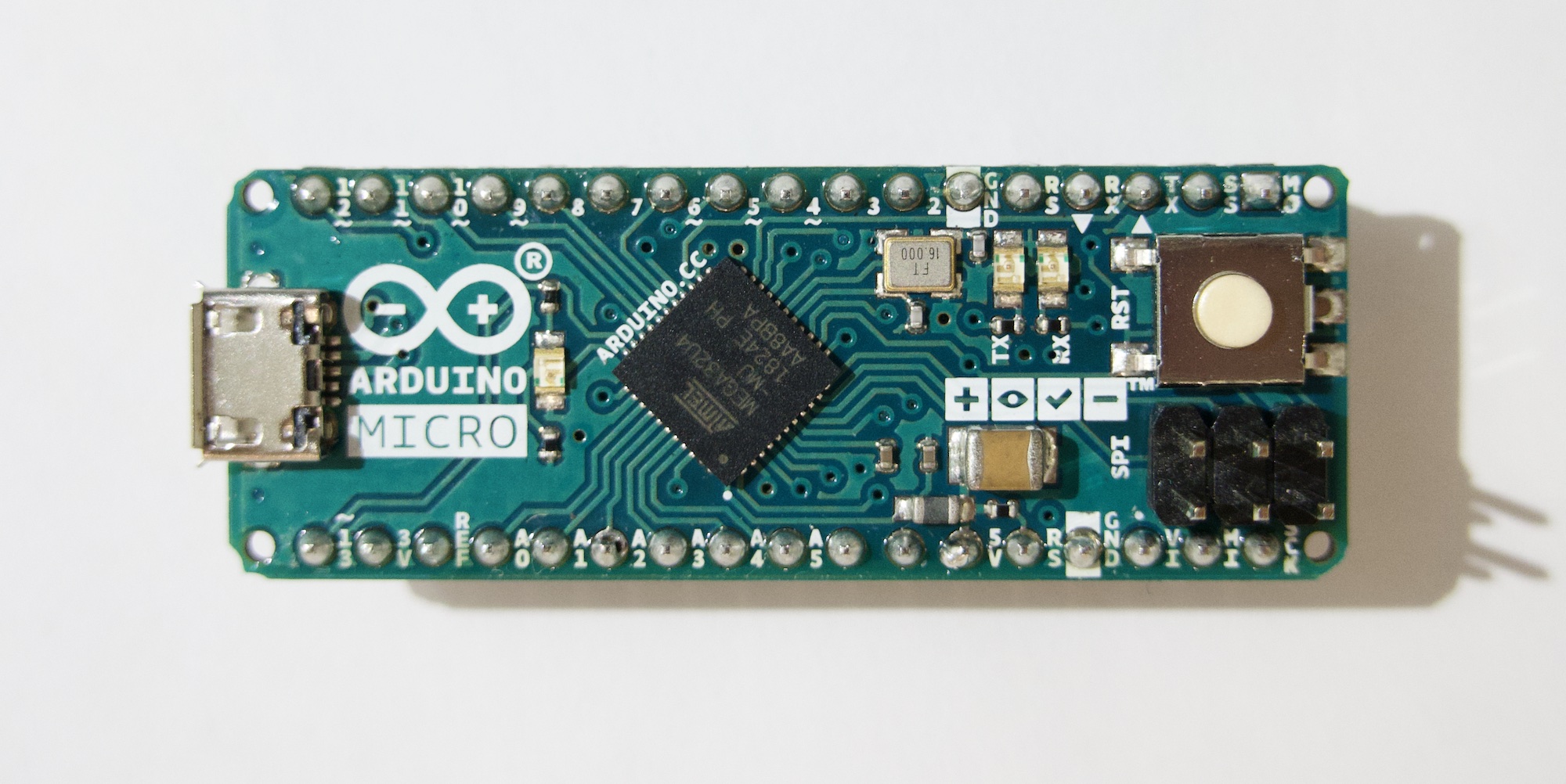
The image below is my Arduino Micro and we can see that from right to left on the top bank, the third and fourth pin are the TX and RX pin.
Next, we need to connect them as the image demonstrates below.
Now we have done the physical part, time to move on to the software part.
2. Set up Raspberry Pi
If you are running Raspian/Ubuntu on your Raspberry Pi, then you need to do these things,
(a) For Raspian users, sudo raspi-config and enter in interface options, choose P6 - Serial Port. Select "NO" for the prompt that asks whether you'd like a login shell over the serial port and select "YES" for the prompt that asks whether you'd like the serial port hardware to be enabled.
For Ubuntu users to achieve the same goal, you need to run the following command
sudo systemctl disable [email protected]
(b) Use your favourite editor to edit /boot/cmdline.txt (for Ubuntu users, edit /boot/firmware/cmdline.txt) from something like
console=serial0,115200 console=tty1 root=PARTUUID=067e19d7-02 rootfstype=ext4 elevator=deadline fsck.repair=yes rootwait
to
console=tty1 root=PARTUUID=067e19d7-02 rootfstype=ext4 elevator=deadline fsck.repair=yes rootwait
i.e., delete console=serial0,115200 (or sometimes it can be console=ttyAMA0,115200, which depends on your previous settings)
(c) Confirm your have enable_uart=1 in /boot/config.txt (for Ubuntu users, check that in /boot/firmware/config.txt)
(d) Reboot your Raspberry Pi.
3. Test UART Connection
Here I use 9600 baudrate for testing. You can use higher or different baudrate between your Raspberry Pi and Arduino Micro. Below is the code I used on Arduino Micro.
char msg[512] = {'\0'};
int index = 0;

void setup() {
  Serial.begin(9600);
  pinMode(LED_BUILTIN, OUTPUT);
  Serial.println("setup Serial");

  Serial1.begin(9600);
  Serial1.println("Hello, Pi!");
}

void loop() {
  while (Serial1.available() > 0) {
    int data = Serial1.read();
    if (data == '\n') {
      msg[index] = '\0';
      Serial.println(msg);
      index = 0;
    } else {
      msg[index] = (char)data;
      index++;
      if (index == 512) {
        index = 0;
        Serial.print(msg);
      }
    }
  }

  Serial1.println("Hello, Pi!");
  digitalWrite(LED_BUILTIN, HIGH);   // turn the LED on (HIGH is the voltage level)
  delay(1000);                       // wait for a second
  digitalWrite(LED_BUILTIN, LOW);    // turn the LED off by making the voltage LOW
  delay(1000);                       // wait for a second
  Serial.println("loop end");
}
And the code I used on Raspberry Pi. (You may need to run sudo systemctl stop [email protected] to stop getty on ttyS0)
For Raspian users, you may need to replace ttyS0 in the following code with serial0.
#!/usr/bin/python3
# -*- coding: utf-8 -*-

import serial

if __name__ == '__main__':
    port = serial.Serial("/dev/ttyS0", baudrate=9600, timeout=3.0)
    msg = []
    while True:
        data = port.read()
        if data == b'\n':
            print("".join(msg))
            port.write(b'Hello, Arduino!')
            msg = []
        else:
            msg.append(str(data, 'utf-8'))
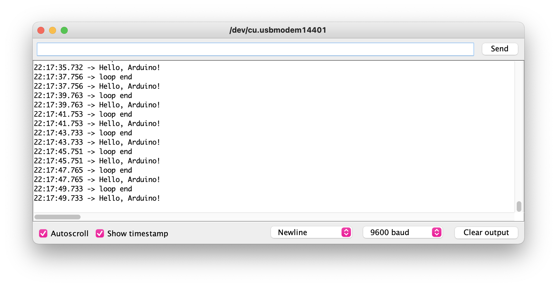
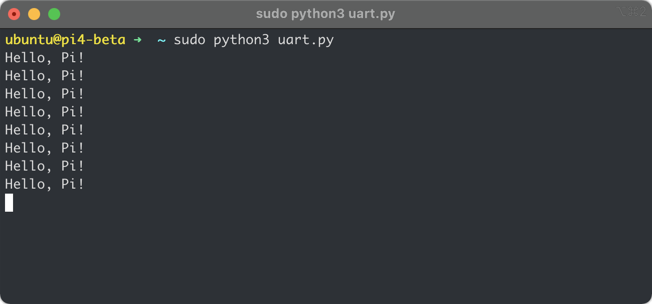
You can see the result below.