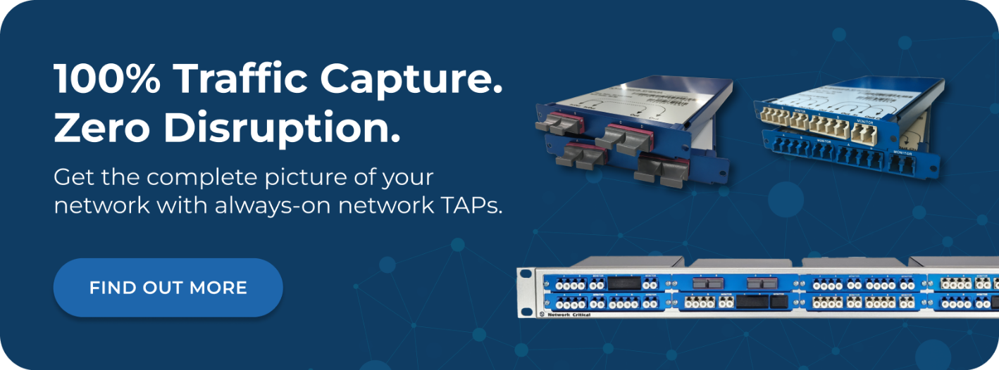






If your organization runs fiber optic cabling, you need a way to give security and monitoring tools access to traffic on those links without disrupting the network. An optical network Test Access Point (TAP) solves that problem by passively splitting the light signal traveling through a fiber cable, creating an exact copy of all traffic and sending it to your tools while the live network continues to operate completely undisturbed. Unlike Switch Port Analyzer (SPAN) ports, which rely on switch software to mirror traffic and are prone to packet drops, optical TAPs work at the physical layer. They require no power, no configuration, and no IP or MAC address. They're invisible to the network and to any attacker probing your infrastructure. The copy they produce is complete and accurate, including errors and malformed frames that SPAN ports typically discard. This article covers exactly how optical TAPs work, the types available, how to choose the right one, and why they're the preferred access method for organizations that need reliable, high-fidelity network visibility on fiber links. An optical network TAP is a purely passive optical device. It contains no active electronics, no firmware, and no software. Instead, it uses a precisely calibrated optical splitter, typically a prism or fused-fiber coupler, to divide the light traveling through a fiber link into two paths: one continues along the live network, and the other diverts to your monitoring port. Fiber optic cables transmit data as pulses of light. When you insert an optical TAP into a link, it intercepts that light and splits it using an internal optical coupler. The split is defined by a ratio, for example 50:50, 60:40, or 70:30. In a 50:50 configuration, half of the available light budget continues to the live network and half goes to the monitoring output port. In a 70:30 configuration, 70% stays on the live network and 30% goes to your tool. The choice of split ratio matters because sending light to the monitor port reduces the power available to the live link. Your network engineer needs to verify that the remaining light is sufficient to maintain the link, factoring in cable runs, connectors, and the receiver sensitivity of your network equipment. Fiber links are full-duplex, meaning they use separate fibers for transmit and receive. A single optical TAP handles both directions simultaneously, delivering separate transmit and receive streams to the monitoring tool. This is an important distinction from SPAN ports: a SPAN configuration requires two ports to capture both directions of traffic on a full-duplex link, whereas a single optical TAP handles this natively. Because the splitting mechanism is entirely passive optics, an optical TAP requires no power to function. There is no power supply to fail, no firmware to crash, and no configuration to misconfigure. If your data center loses power completely, the TAP continues to pass traffic on the live link without interruption. This makes it a true zero-point-of-failure access method. Not all fiber links are the same, and optical TAPs are designed to match the specific characteristics of different fiber types, connector formats, and speed requirements. Choosing the wrong TAP for your link type will result in signal degradation or an incompatible physical connection. The two fundamental categories of optical fiber require different TAPs: Using a multimode TAP on a singlemode link, or vice versa, will cause excessive signal loss and link instability. Always match the TAP to your fiber type. The most common form factor for enterprise fiber monitoring, LC breakout TAPs split a single fiber link into a separate monitoring output using standard LC connectors. These TAPs are available for both multimode and singlemode fiber and support speeds from 1Gbps to 10Gbps. They're the standard choice for: High-speed 40G and 100G links use multiple fiber strands bundled into a Multi-Fiber Push-On (MPO) connector rather than individual LC connections. MPO TAPs are purpose-built for these high-density, high-bandwidth links and can use up to 24 strands of fiber optic cable within a single connector interface. MPO TAPs provide a key flexibility advantage: they can monitor the aggregate 40G/100G link while also supporting breakout connections that allow individual 1G/10G channels to be tapped separately. This means the same TAP can serve both today's link speeds and future upgrades without additional hardware investment. Some 40G Cisco environments use Bidirectional (BiDi) transceivers that transmit and receive on different wavelengths over a single fiber strand rather than using separate fibers per direction. Standard TAPs are not compatible with this architecture. BiDi TAPs are purpose-built for these deployments, handling the wavelength-division multiplexing inherent in Cisco's BiDi design while still capturing full-duplex traffic. The most common alternative to optical TAPs for traffic access is the SPAN port (also called a mirror port) available on managed switches. Understanding the fundamental differences helps explain why organizations with serious monitoring requirements choose TAPs. SPAN ports work by having the switch software copy packets from one or more source ports and forward them to a designated monitor port. On fiber uplinks, this creates several problems: An optical TAP operates independently of any switch, router, or network device. Its capture fidelity is not affected by switch load, software versions, or administrator actions: Selecting the right split ratio is a technical decision that balances monitoring fidelity against link health. Getting this wrong can cause the live link to degrade or fail. Every fiber link has a power budget defined by the transmitter output power, the receiver sensitivity, and the losses introduced by cable runs and connectors. An optical TAP adds insertion loss to this budget. The split ratio determines how that loss is distributed between the live link and the monitoring output. The three most common ratios and their typical use cases are: Before selecting a split ratio, calculate your link's power budget. Take the transmitter output power, subtract the cable and connector losses, and verify the result against the minimum receiver sensitivity. The TAP's insertion loss must be accounted for in this calculation. In most short to medium enterprise fiber runs, a 50:50 or 60:40 split is perfectly safe. For long-distance singlemode links approaching their distance limits, a 70:30 split is advisable. Optical TAPs are used across a wide range of network environments wherever fiber links carry traffic that requires monitoring. The use cases span security, compliance, performance management, and operational visibility. The highest-priority TAP locations in most data centers are the core uplinks and distribution-layer interconnects. These links carry aggregated traffic from dozens or hundreds of downstream devices, making them the most efficient insertion points for security monitoring tools. A network TAP at the core captures traffic from across the entire network without requiring monitoring tools to connect to every individual segment. Traffic entering and leaving your network at the internet edge is the primary target of perimeter security tools including firewalls, Intrusion Prevention Systems (IPS), and next-generation threat detection platforms. Placing optical TAPs on the uplinks between your edge router and core switch ensures these tools receive an unmodified copy of all inbound and outbound traffic. Many industries operate under regulatory frameworks that require demonstrable, complete traffic capture. Healthcare organizations must satisfy the Health Insurance Portability and Accountability Act (HIPAA) requirements for data protection. Financial services firms must meet standards including Payment Card Industry Data Security Standard (PCI DSS). In these environments, the guarantee of 100% packet capture that optical TAPs provide is essential. SPAN ports, with their known drop behavior, cannot satisfy this requirement. Telecommunications providers, cloud service providers, and research institutions routinely operate 40G and 100G fiber links. These environments require MPO TAPs capable of capturing full line-rate traffic without introducing any latency or affecting link performance. An optical TAP delivers a raw copy of traffic on a single link. In complex networks with dozens of TAP insertion points, managing where that copied traffic flows requires an additional layer of intelligence. A single security tool cannot process raw traffic from 20 different TAP points simultaneously, and you wouldn't want to connect 20 separate cables to a single tool even if it could. A network packet broker sits between your TAPs and your monitoring tools, aggregating feeds from multiple sources and filtering, deduplicating, and distributing the right traffic to the right tools. This architecture provides several operational benefits: For organizations deploying visibility infrastructure from scratch or expanding an existing deployment, hybrid TAP and packet broker platforms combine both functions in a single chassis. This reduces rack space, simplifies cabling, and provides a unified management interface for both the access layer and the distribution layer of your visibility architecture. When comparing optical TAPs, the technical specifications that matter most to network performance and monitoring fidelity are: Because an optical TAP is entirely passive, it has no awareness of whether a monitoring tool is connected to its output port. If the tool fails, is disconnected, or is powered off, the TAP continues to pass traffic on the live link without any change. There is no impact on live network traffic under any monitoring tool condition. Yes. An optical TAP operates at the physical layer and captures every bit of the optical signal, regardless of what the payload contains. Encryption is a higher-layer function. The TAP captures the encrypted frames exactly as they traverse the link. Decryption, if required, happens in your monitoring tools or a dedicated SSL/TLS inspection appliance downstream of the TAP. No. Optical TAPs are rated for specific link speeds because the optical characteristics and fiber connector types differ across speed grades. A TAP rated for 10G should not be used on a 40G or 100G link. The physical connectors alone will typically prevent incorrect installation, but you should always verify the TAP specification against your link speed before ordering. Directly, a monitoring tool can only accept as many inputs as it has physical ports. However, a network packet broker aggregates feeds from multiple TAPs and forwards a filtered or combined stream to a tool. This allows a single tool to receive relevant traffic from dozens of TAP insertion points simultaneously. They use the same underlying optical splitting principle, but a TAP is engineered specifically for network monitoring deployments with appropriate insertion loss specifications, duplex handling, and rack-mountable form factors. A generic fiber splitter is not a substitute for a TAP in a production network monitoring environment. Network Critical has designed and manufactured optical TAPs since 1997, with a range engineered for every fiber type, speed, and deployment scenario in modern enterprise and service provider networks. Our passive fiber TAPs cover 1G/10G multimode and singlemode LC links, 40G/100G MPO deployments, and Cisco BiDi infrastructure, with insertion loss as low as 1.3dB and split ratio options of 50:50, 60:40, and 70:30 to match your link's power budget. Where networks require aggregation and intelligent traffic distribution, our SmartNA-XL combines TAP access with full packet broker functionality in a modular 1RU chassis supporting 1G/10G/40G. The SmartNA-PortPlus scales this capability up to 100G and beyond, with a non-blocking 1.8 Tbps architecture and scalability from 1RU to 5RU for the largest data center deployments. Whether you're deploying visibility on a handful of core uplinks or building out a comprehensive monitoring architecture across a multi-site network, our team can help you select the right TAPs, split ratios, and aggregation platform for your specific environment. Get in touch to discuss your requirements.
How an Optical TAP Works
The Light-Splitting Mechanism
Full-Duplex Traffic Capture
No Power, No Address, No Failure Point
Types of Optical Network TAPs
Multimode vs. Singlemode TAPs
LC Breakout TAPs for 1G/10G Links
Multi-Fiber Push-On TAPs for 40G/100G Links
Bidirectional TAPs for Cisco BiDi Infrastructure
Optical TAPs vs. SPAN Ports: Why the Difference Matters
How SPAN Ports Fall Short on Fiber Links
What Optical TAPs Guarantee
Optical TAP Split Ratios Explained
Understanding the Light Budget
When to Involve a Network Engineer
Deployment Scenarios for Optical TAPs
Data Center Core and Distribution Links
Internet Edge and Perimeter Security
Compliance and Lawful Interception
High-Speed Research and Service Provider Networks
Combining Optical TAPs with a Network Packet Broker
Why Aggregation and Filtering Are Necessary
The Hybrid TAP and Packet Broker Approach
Key Specifications to Evaluate When Choosing an Optical TAP
Frequently Asked Questions
What Happens to the Live Network if the Monitoring Tool Fails or Is Disconnected?
Do Optical TAPs Work with Encrypted Traffic?
Can You Use an Optical TAP on a Link Running at a Different Speed Than the TAP's Rated Speed?
How Many TAPs Can You Run into a Single Monitoring Tool?
Is a Passive Optical TAP the Same as a Fiber Splitter?
How Network Critical Can Help