






Discover how to design tailored multicloud connectivity scenarios with Megaport and Megaport Cloud Router (MCR). From physical layer configurations to cloud-specific connectivity options, explore resilient and scalable architectures that simplify network complexity. Gain insights into HA designs, dual data center strategies, and step-by-step guidance for building a better network.
How to define requirements, then design different multicloud scenarios, using Megaport and Megaport Cloud Router.
If you are a loyal reader of our blog, you likely came across one of our popular posts, Nine Common Scenarios for Multicloud Design, illustrating different options to connect from on-premises infrastructure to CSPs with or without Megaport Cloud Router (MCR). Over the year and a half since it was released, we have worked with a large number of customers adapting the common scenario designs. We have taken their input, added some improvements to Megaport’s global network, and produced a new set of design scenarios that are focused on diversity and design principles, which we will discuss in this article.
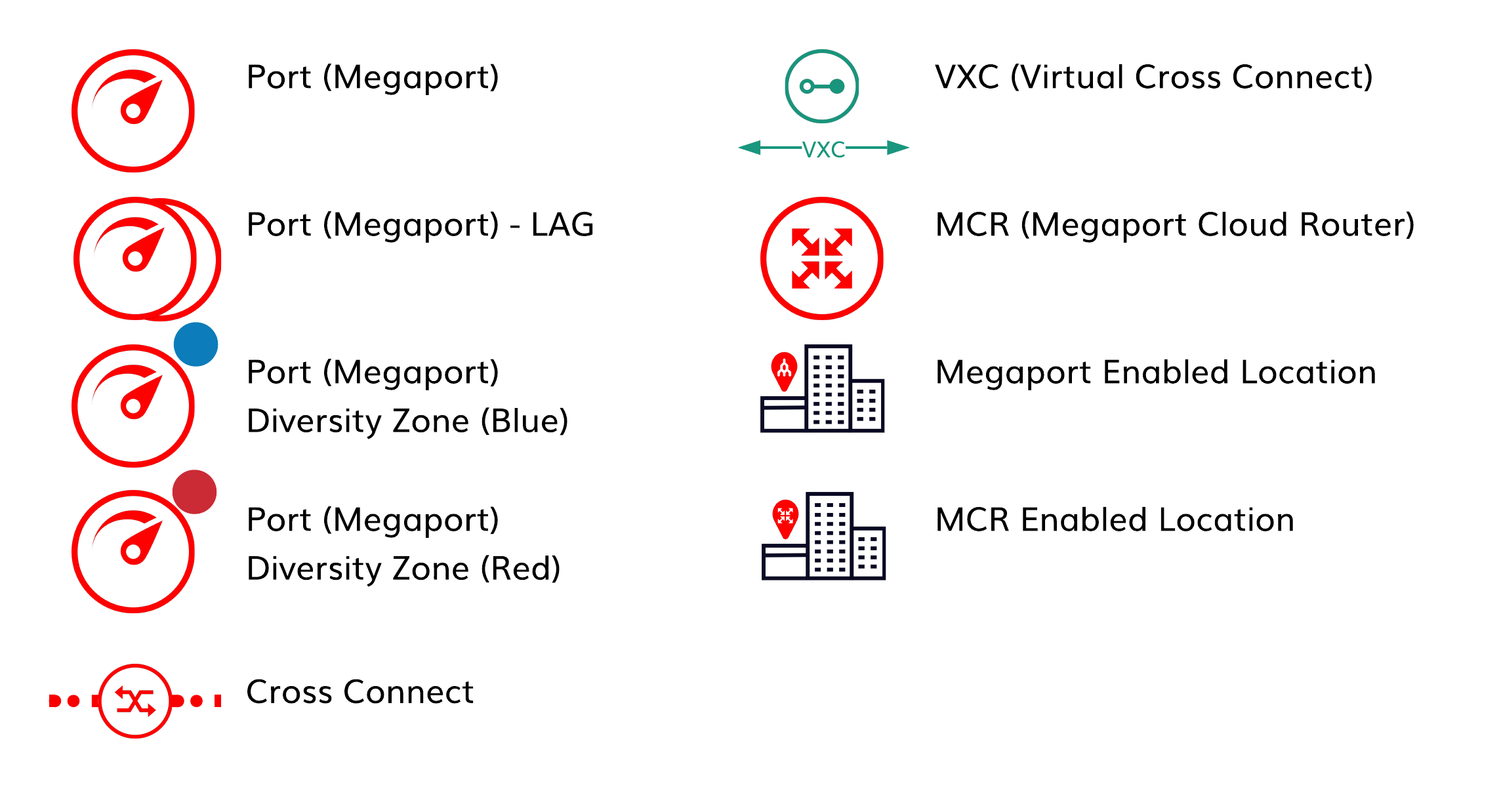
Before we get started, here’s a legend to help you decipher the symbols in the designs we’ll review.
To begin, we need to establish your physical location in a colocation DC, and determine whether they are a Megaport-enabled location. Next, you should decide how much protection you would like to build into your overall design at the physical layer, as this will make a difference on the commercials.
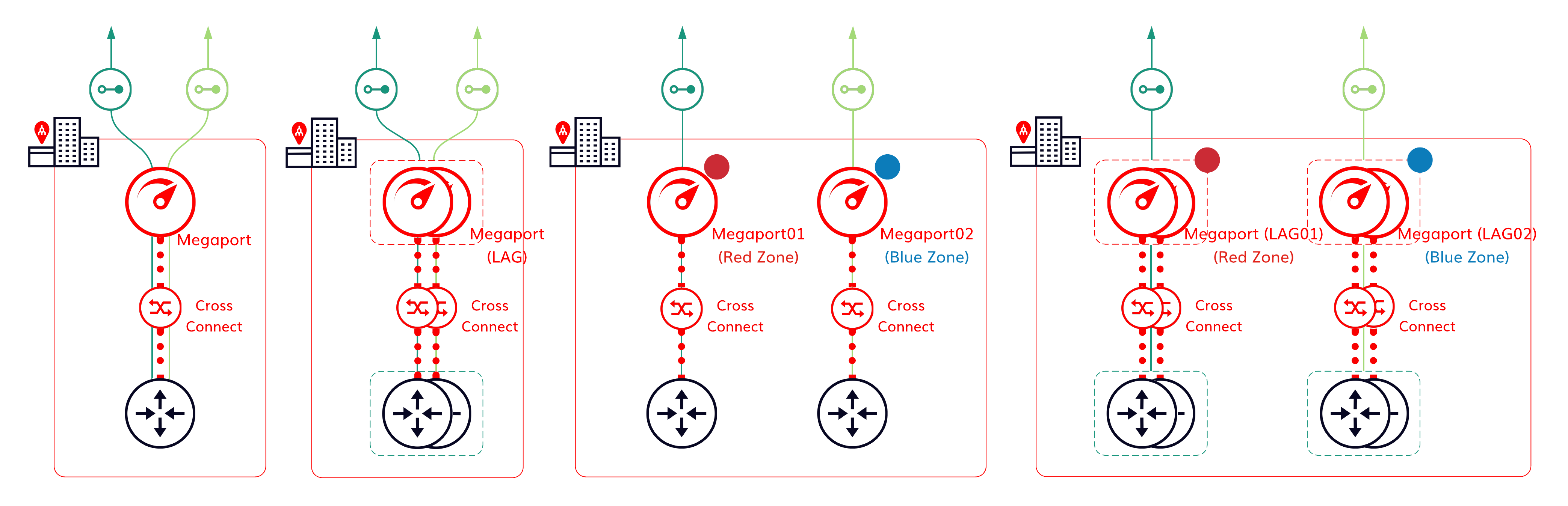
From left to right, above, illustrates different configurations from a single Megaport to dual Megaports in a LAG in two different diversity zones within a single DC. You can learn more about the different common physical connectivity options at Common Connectivity Scenarios.
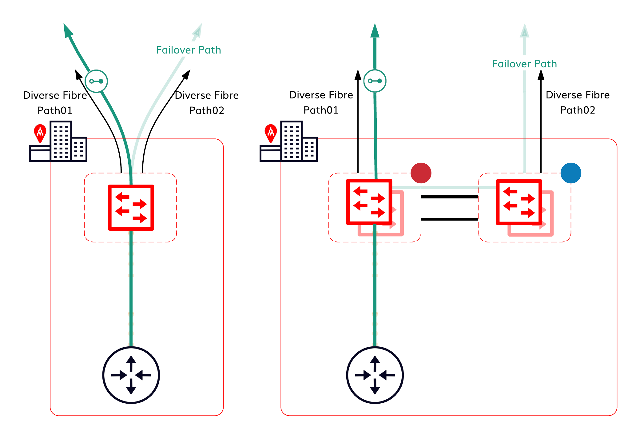
After you determine the different device level diversity options you need, we can discuss the protection that you will get by default with a standard VXC to your destination. For each of the DCs that Megaport is installed in globally, each DC by default will have two or more diverse fibre connected into the Megaport global backbone network. Each of the VXCs will be protected by all the available fibre paths at the DC, and will automatically failover to the secondary, tertiary path, etc., until there are no more fibre paths available.
We’ve covered the physical layer diversity options and protections you get from a VXC; let’s take a look at the cloud connectivity options. Each Cloud Service Provider (CSP) typically will have a connectivity model that will have physical diversity built into it at each of the metro or DC locations that meets the Megaport network.
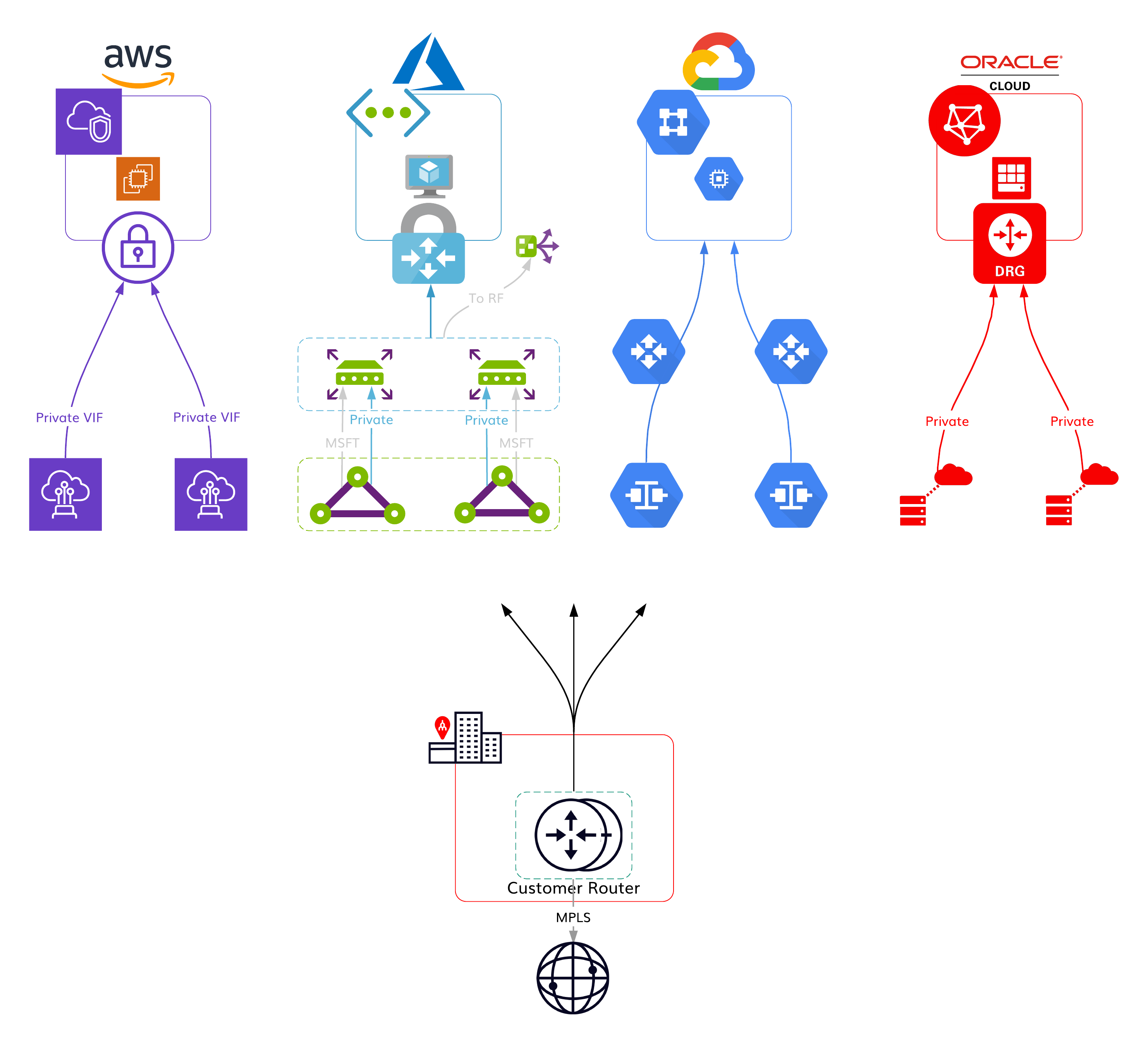
The best diversity option for AWS is delivered over the Hosted Connection option. (Find out more at Diversity in AWS Connections.) There are other diversity options available with Hosted VIF and Dedicated options, as well. Please reach out to the Megaport team if you have questions comparing the three options.
Each Azure ExpressRoute circuit in a peering location comes by default with two available on-ramps to connect to (primary and secondary), which are in either the same or a different DC chosen by Microsoft. Azure will only provide an SLA (99.95%) on the circuit if the customer connects to both, and with active BGP sessions over both.
The customer has the choice of selecting a redundant pair or a single Partner Interconnect in a single interconnect location, and only the redundant pair or better gets the GCP SLA (99.9% - 99.99%, depending on deployment model).
The customer has the choice of deploying a single FastConnect or two at a single region, and only the redundant pair gets the OCI SLA (99.9%).
After determining the physical layer and cloud connectivity, the next thing you will need to consider is whether an MCR is suitable for your design. Here are some key considerations to help you decide.
Whether you are deploying a cloud-only solution that does not require on-premises infrastructure.
Your physical geographical distance to the CSPs — the farther away you are, the more an MCR will help with performance cloud-to-cloud.
Do you wish to offload the responsibility of joining multiple cloud/on premises targets together?
Do you wish to simplify the deployment by leveraging Megaport auto deployment integrations with the CSPs?
Are you simplifying the different network protocols requirement to achieve cloud connectivity such as BGP, Q-in-Q?
Are you deploying a cloud connectivity option that requires public IP address and public ASN, and you do not own any?
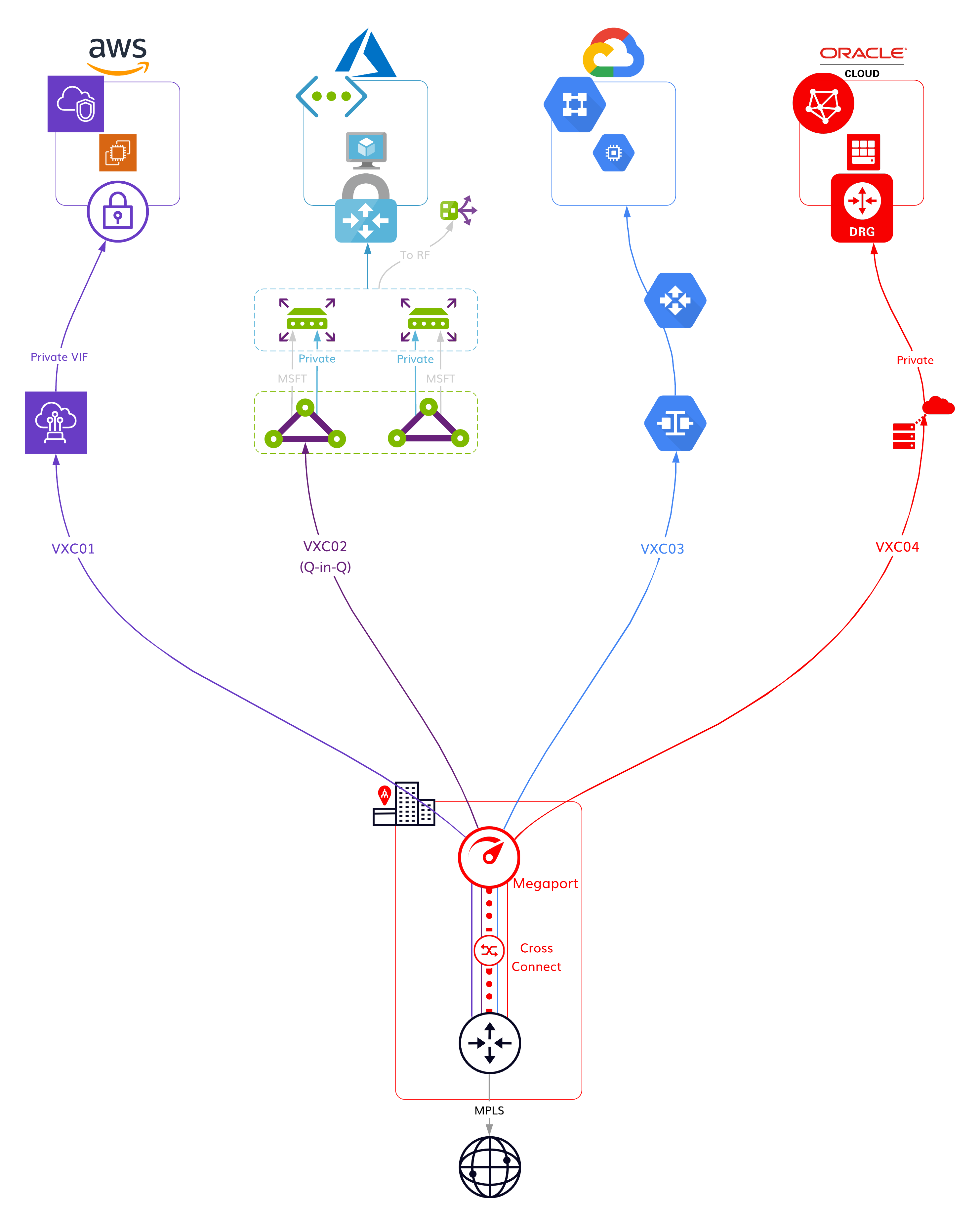
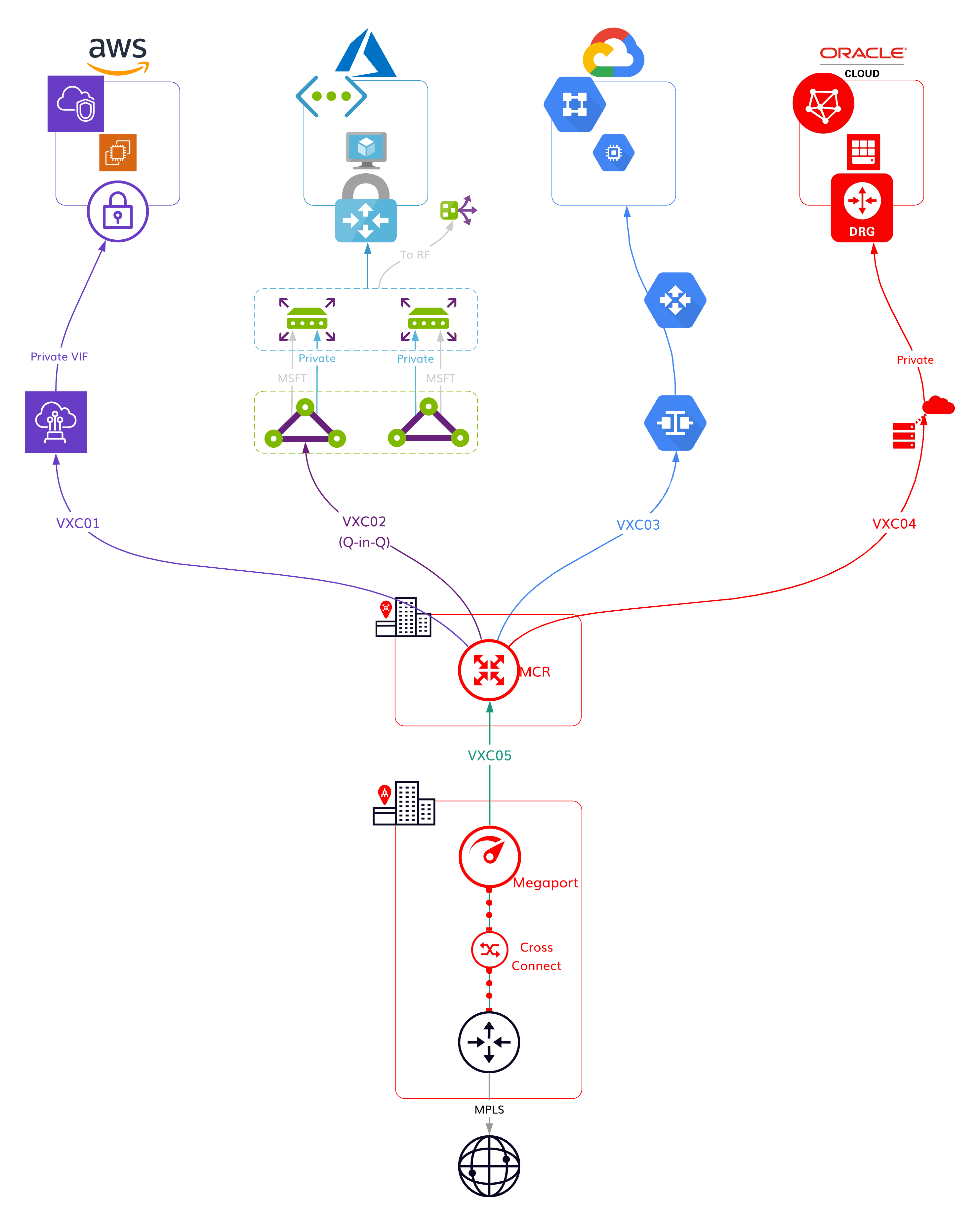
Traffic between CSPs and on-premises colocation DC (L3 via MCR)(Diagram showing L3 traffic flow)
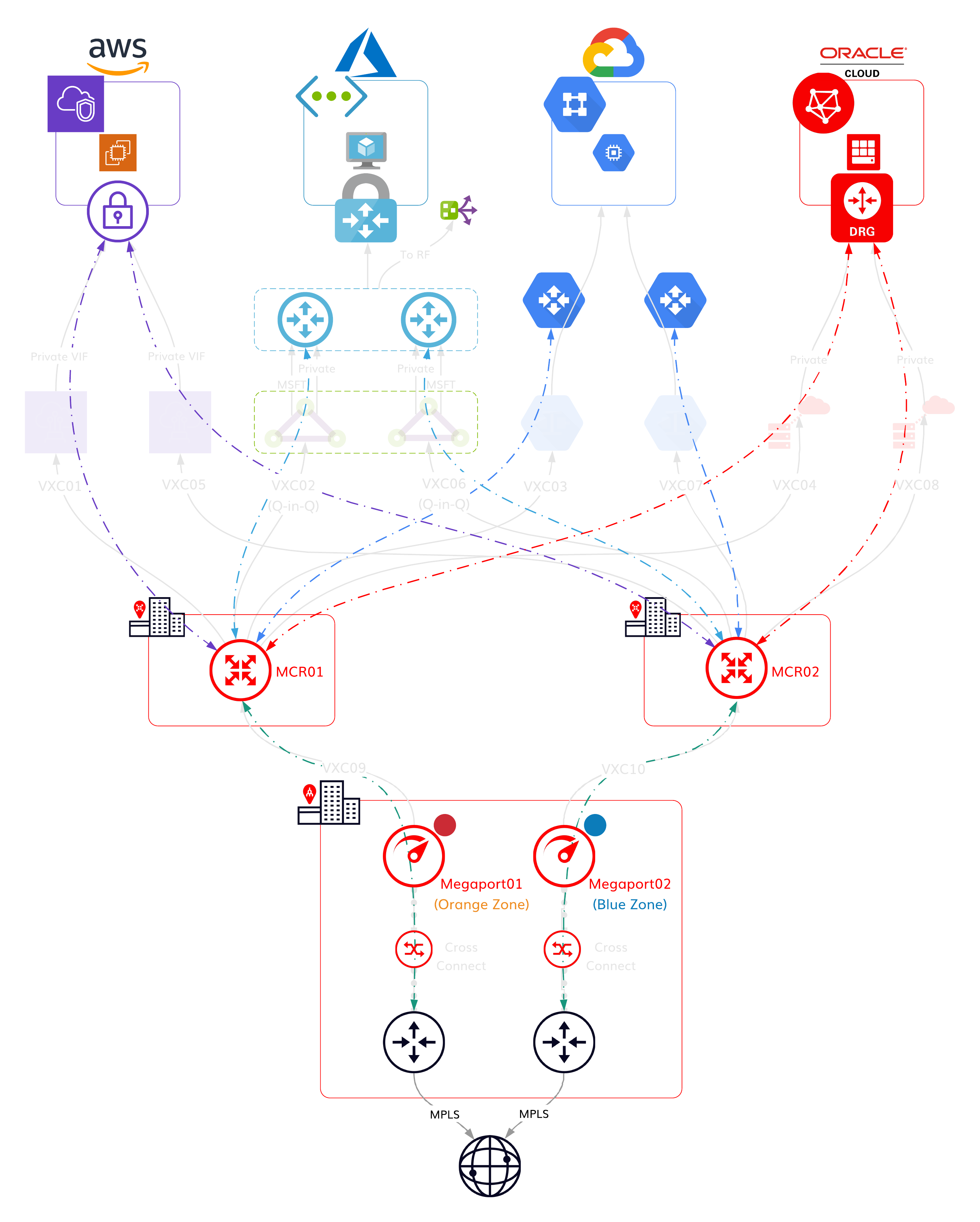
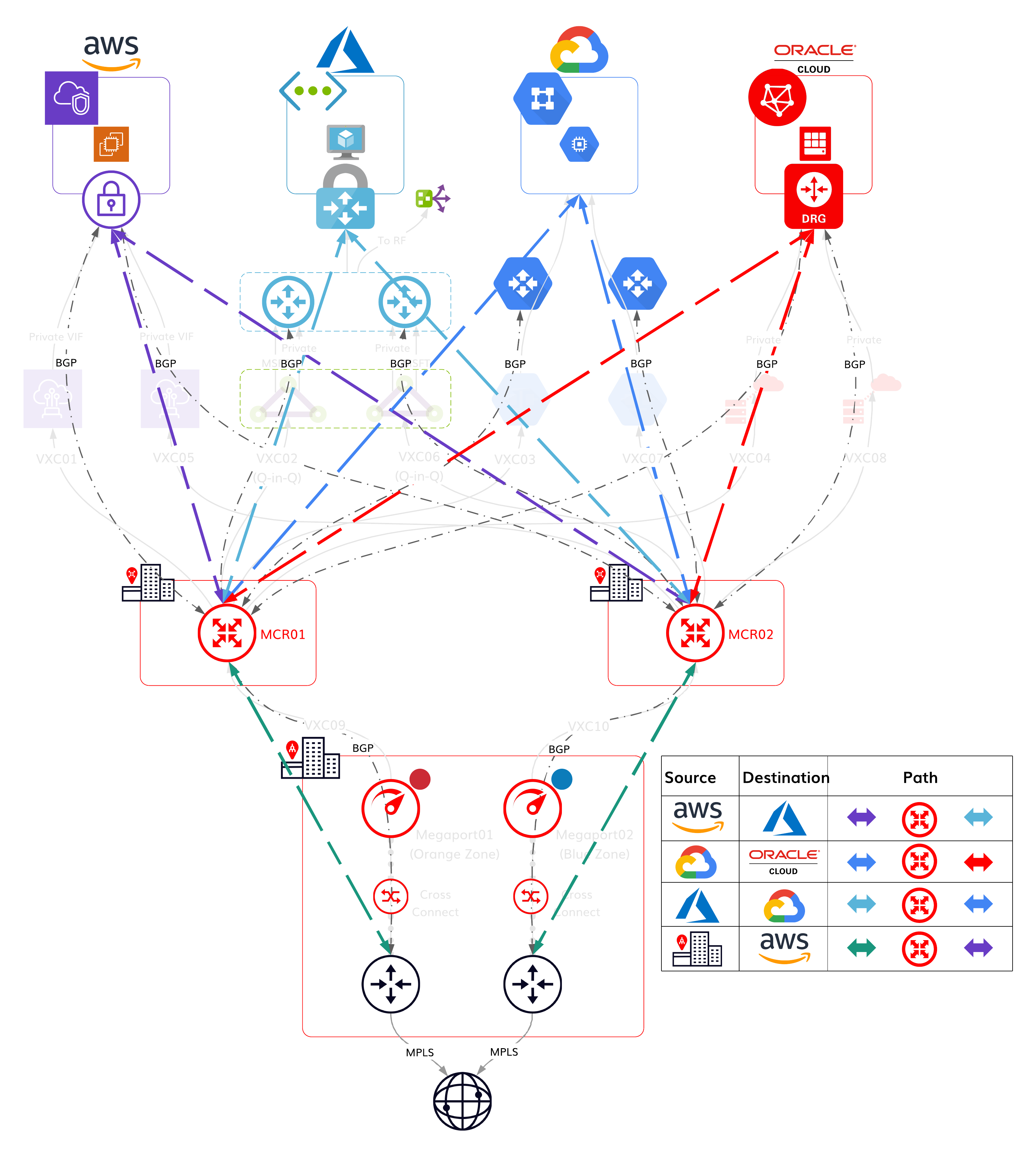
When we are discussing network design, it is often easy to think you just need the best possible protection you can get. Unfortunately, that could easily blow out your budget and it might not make sense technically, either. There are a few things to consider to determine what is the suitable level of resiliency for your Megaport design.
To begin with, let’s assume that you have a single VXC over a single Megaport to a destination target, from which you receive protection provided by the diverse fibre paths.
Next, you will need to think about:
Lastly:
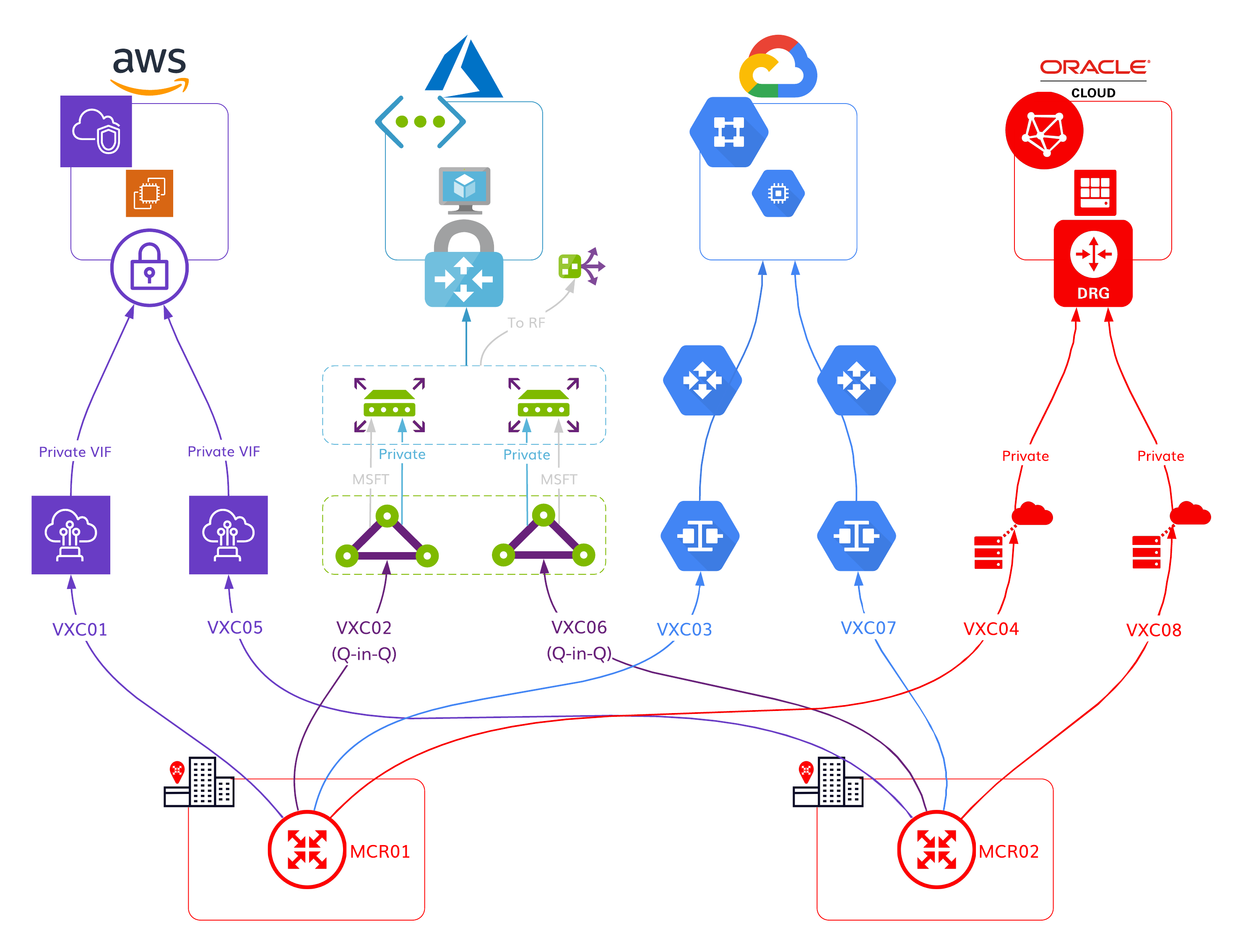
Dual MCRs as hubs connecting CSPs together in HA configuration
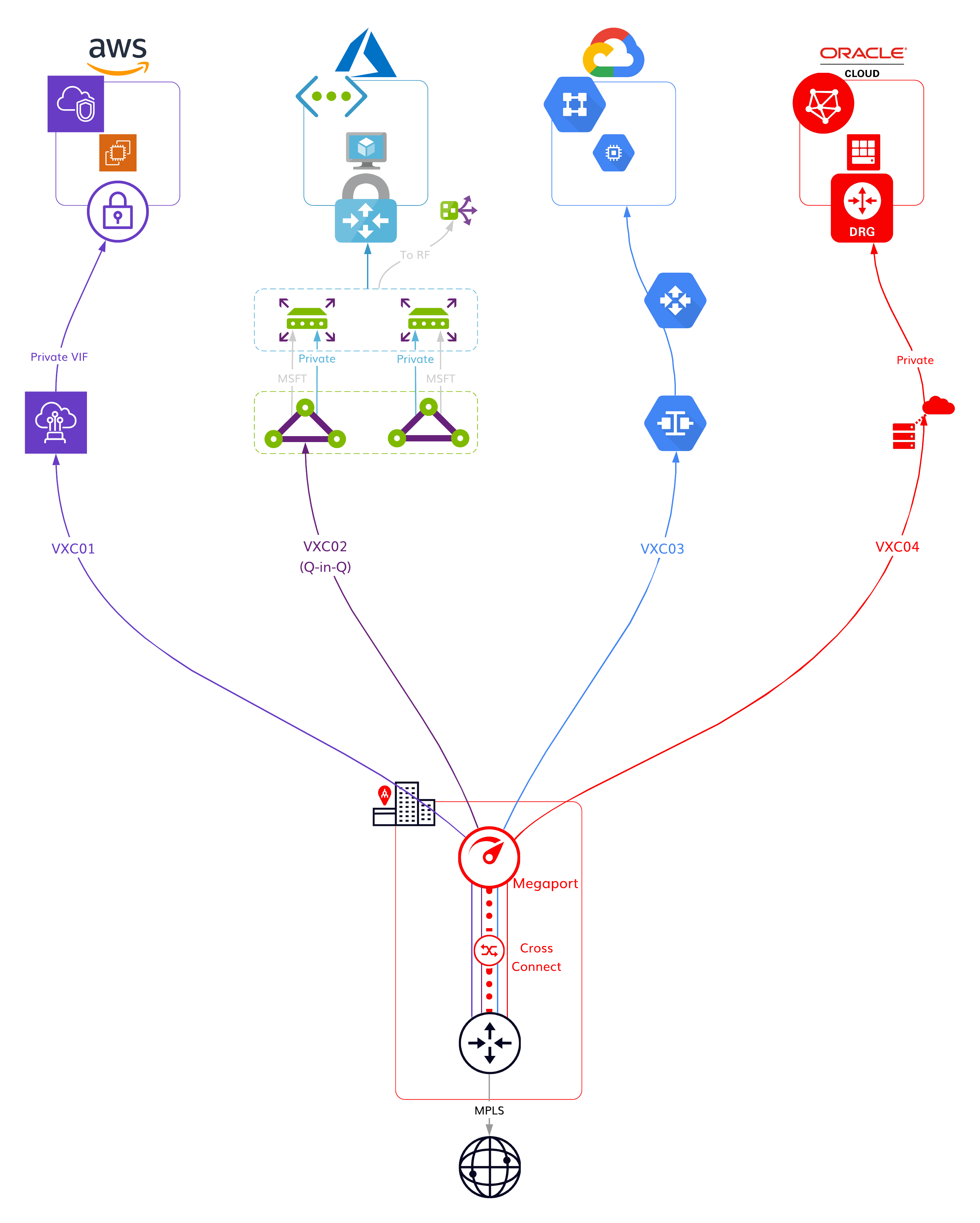
Single Megaport connecting to each CSP
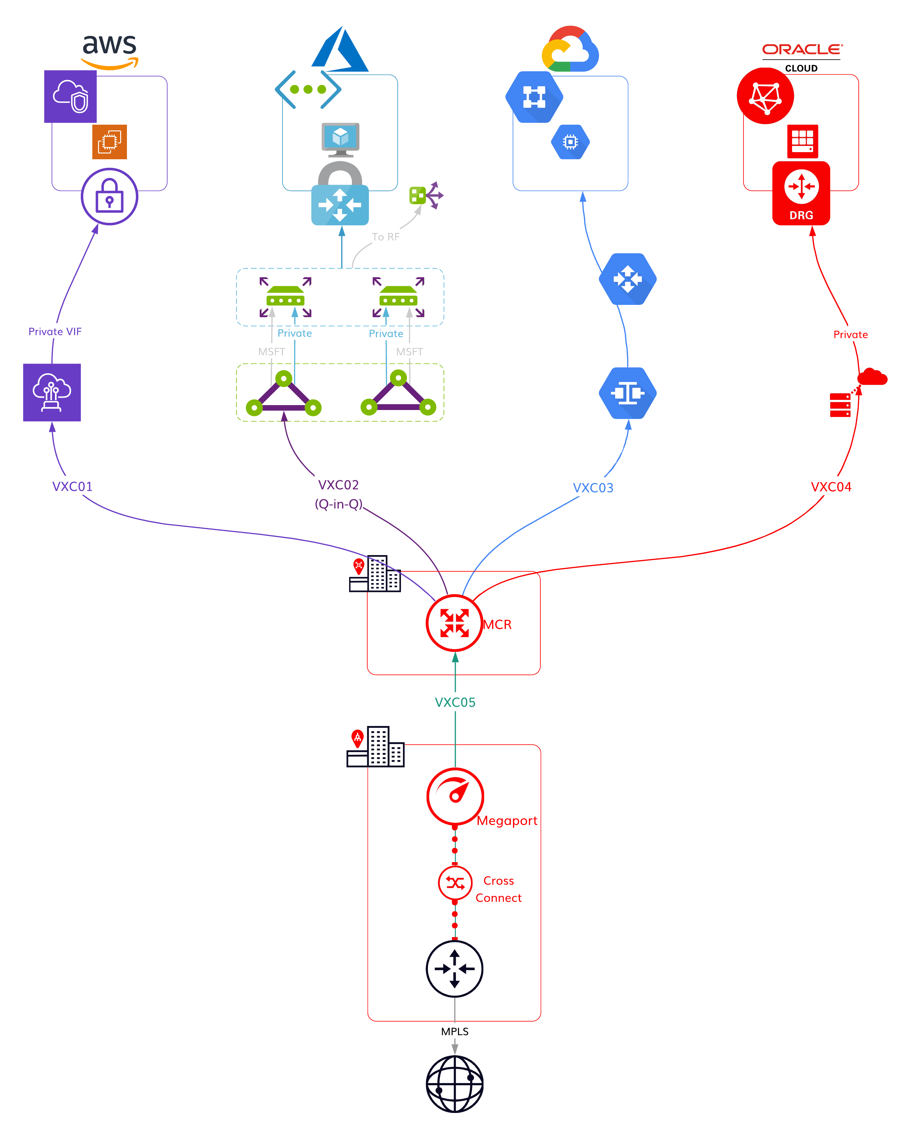
MCR as hub connecting DC (Single Megaport) and CSPs together
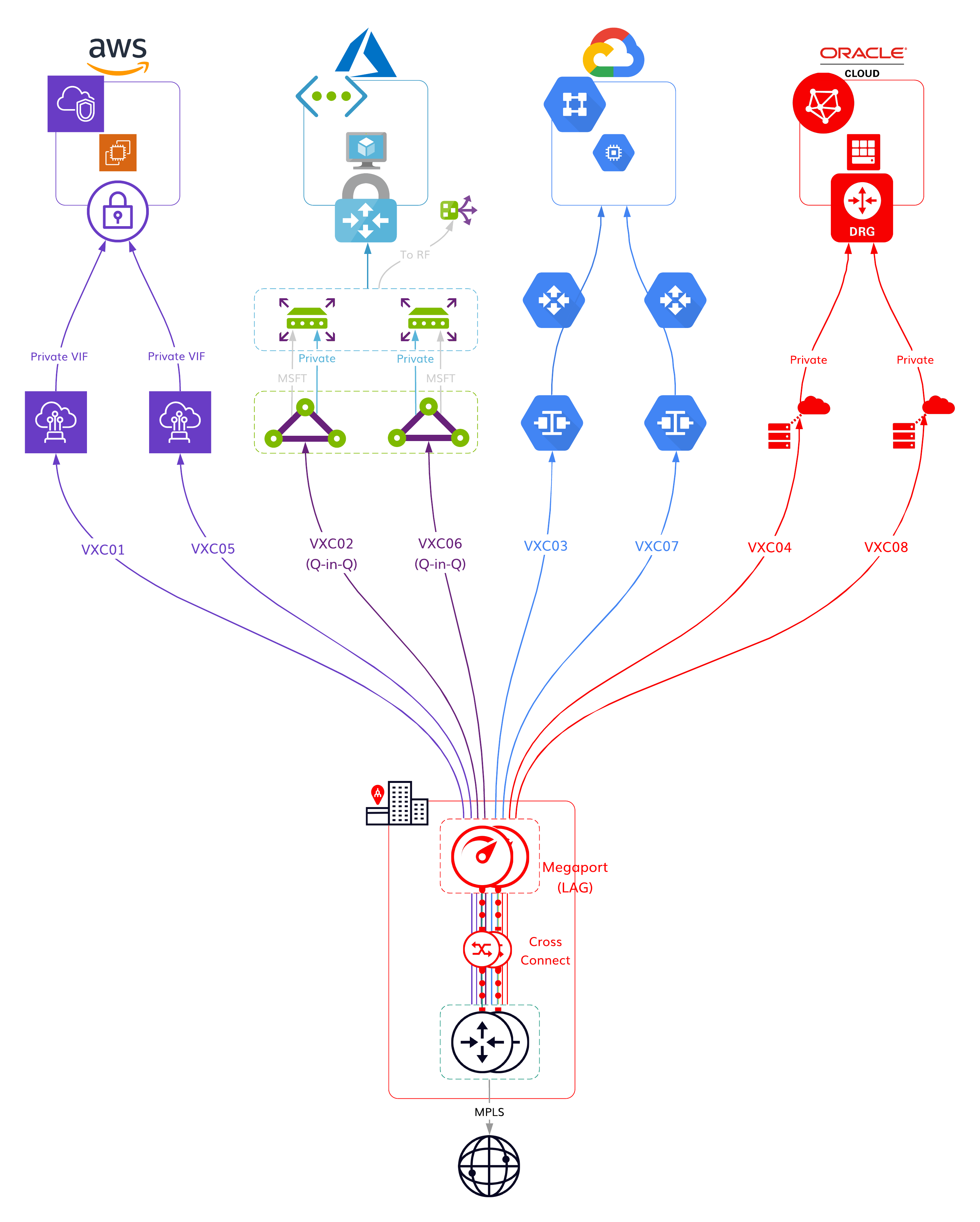
Dual Megaport in LAG connecting to each CSP in HA configuration
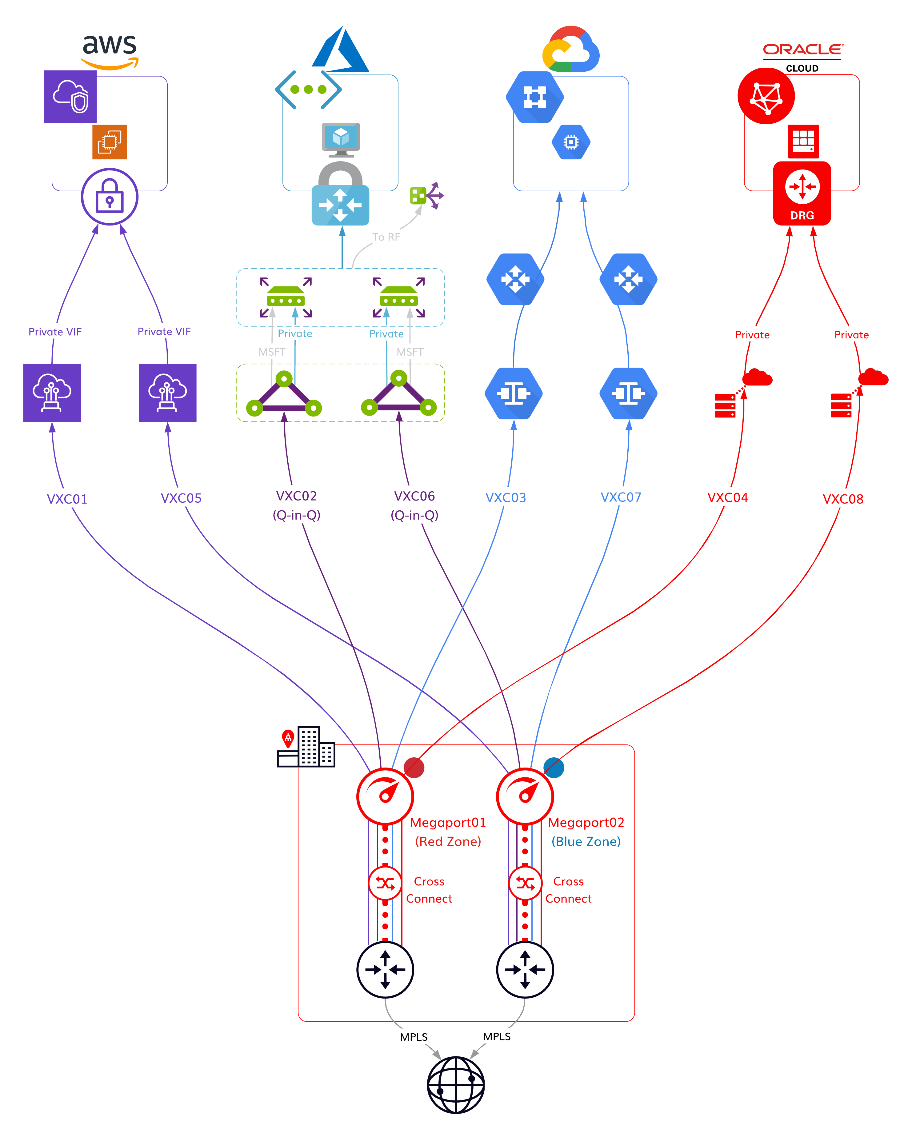
Megaport in each Diversity Zone connecting to each CSP in HA configuration
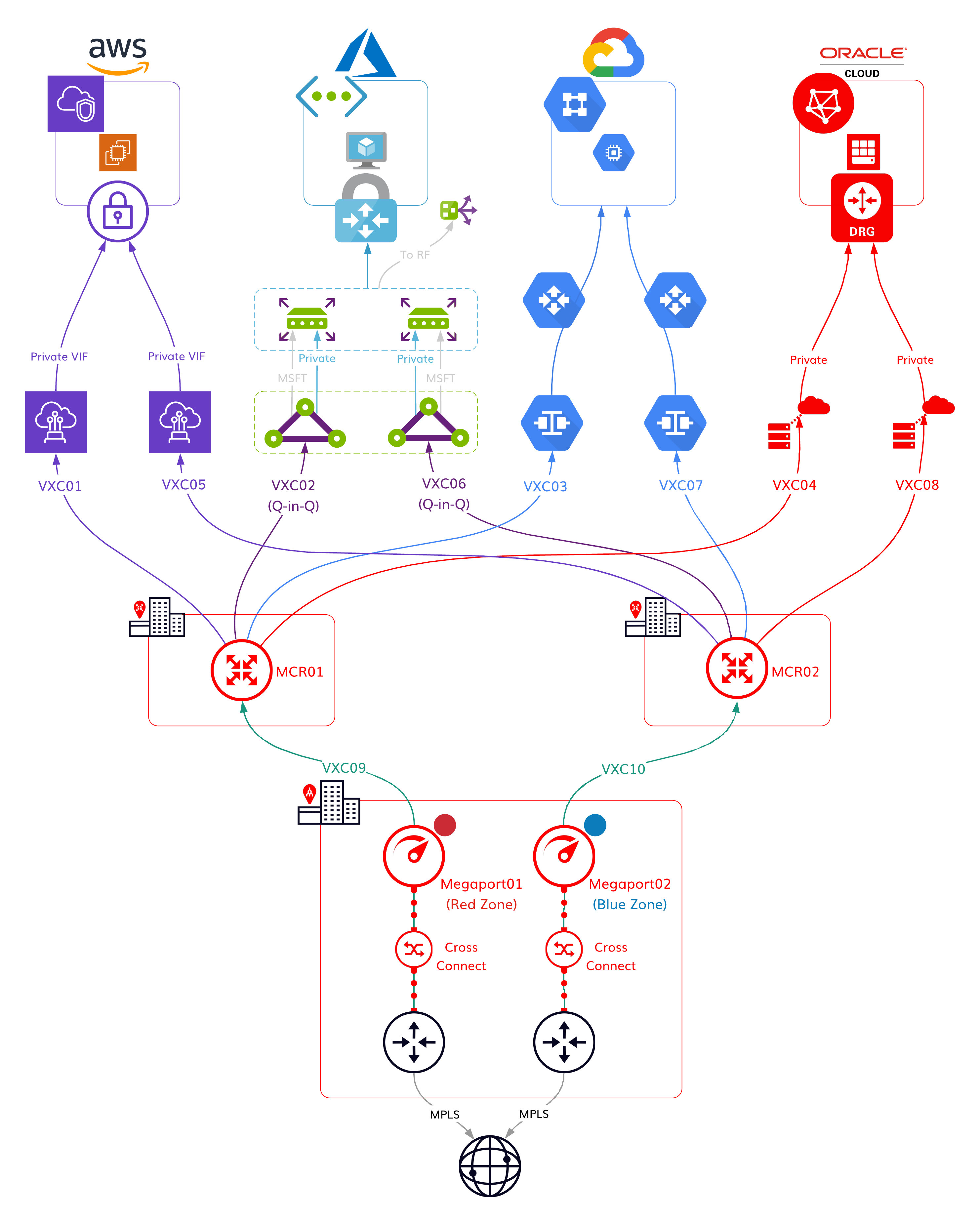
Dual MCRs as hubs connecting DC with Megaport in each Diversity Zone, and CSPs in HA configuration
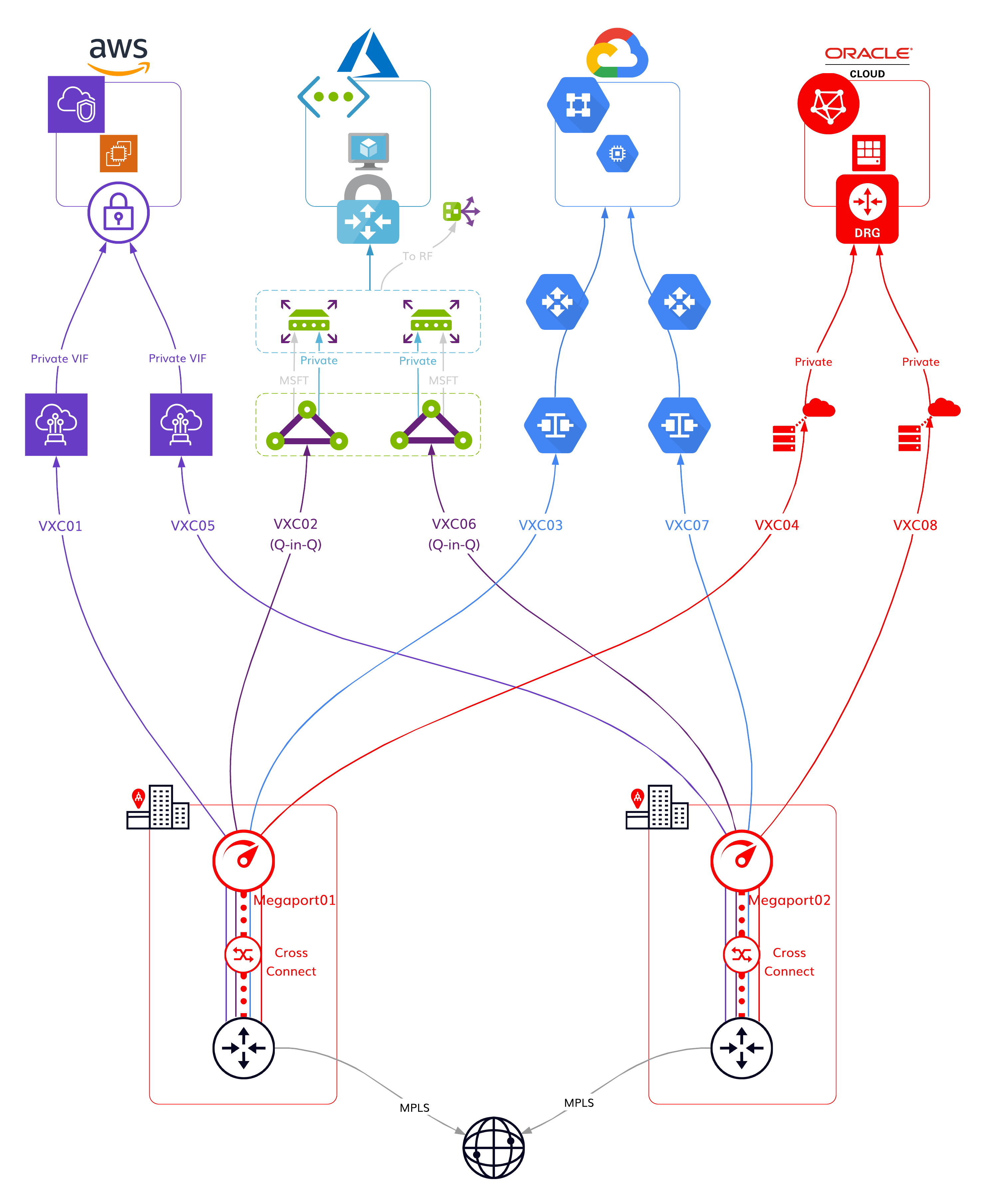
Single Megaport in each DC connecting to CSPs in HA configuration
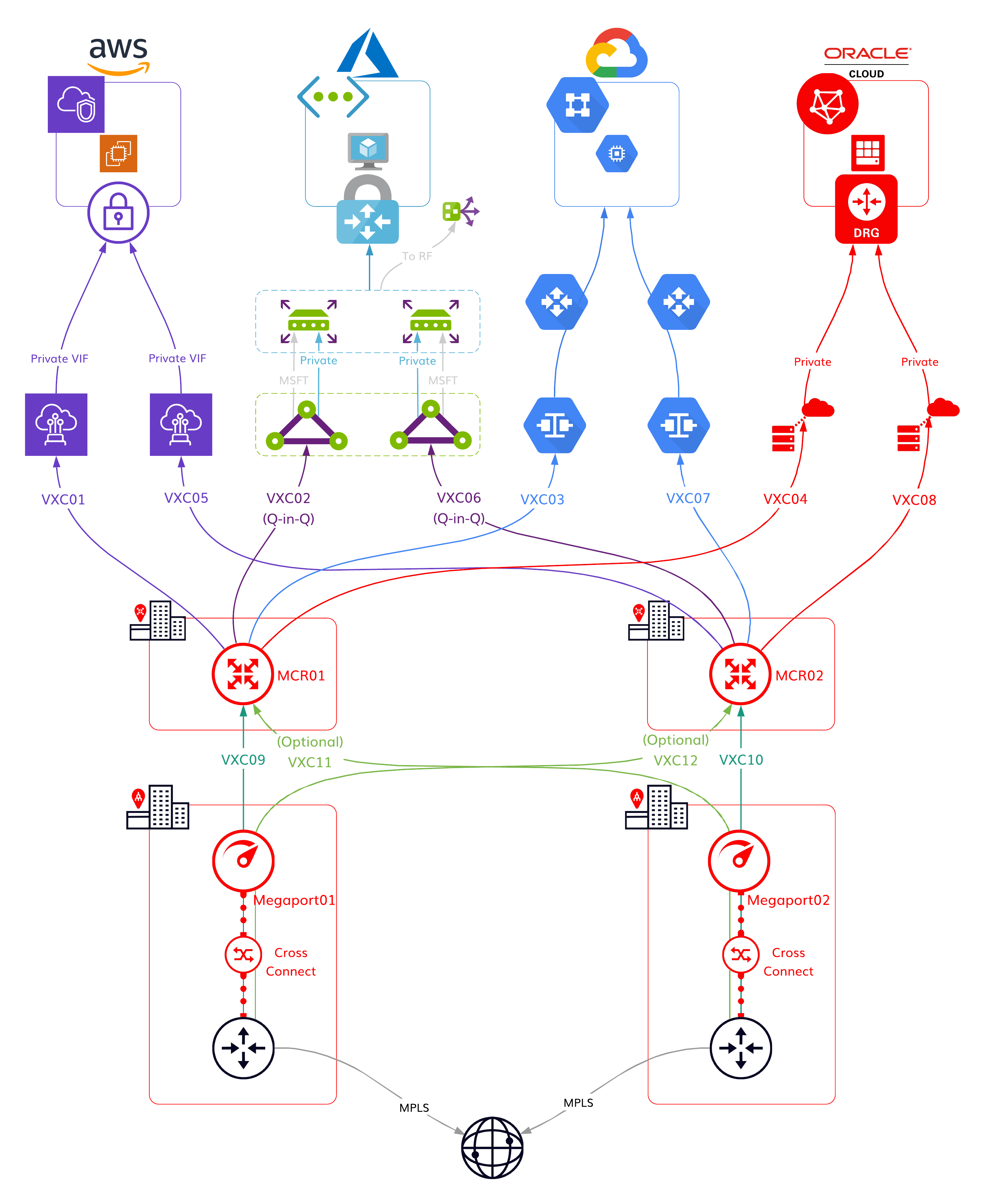
Dual MCRs as hubs connecting DCs with Megaport in each DC, and CSPs in HA configuration
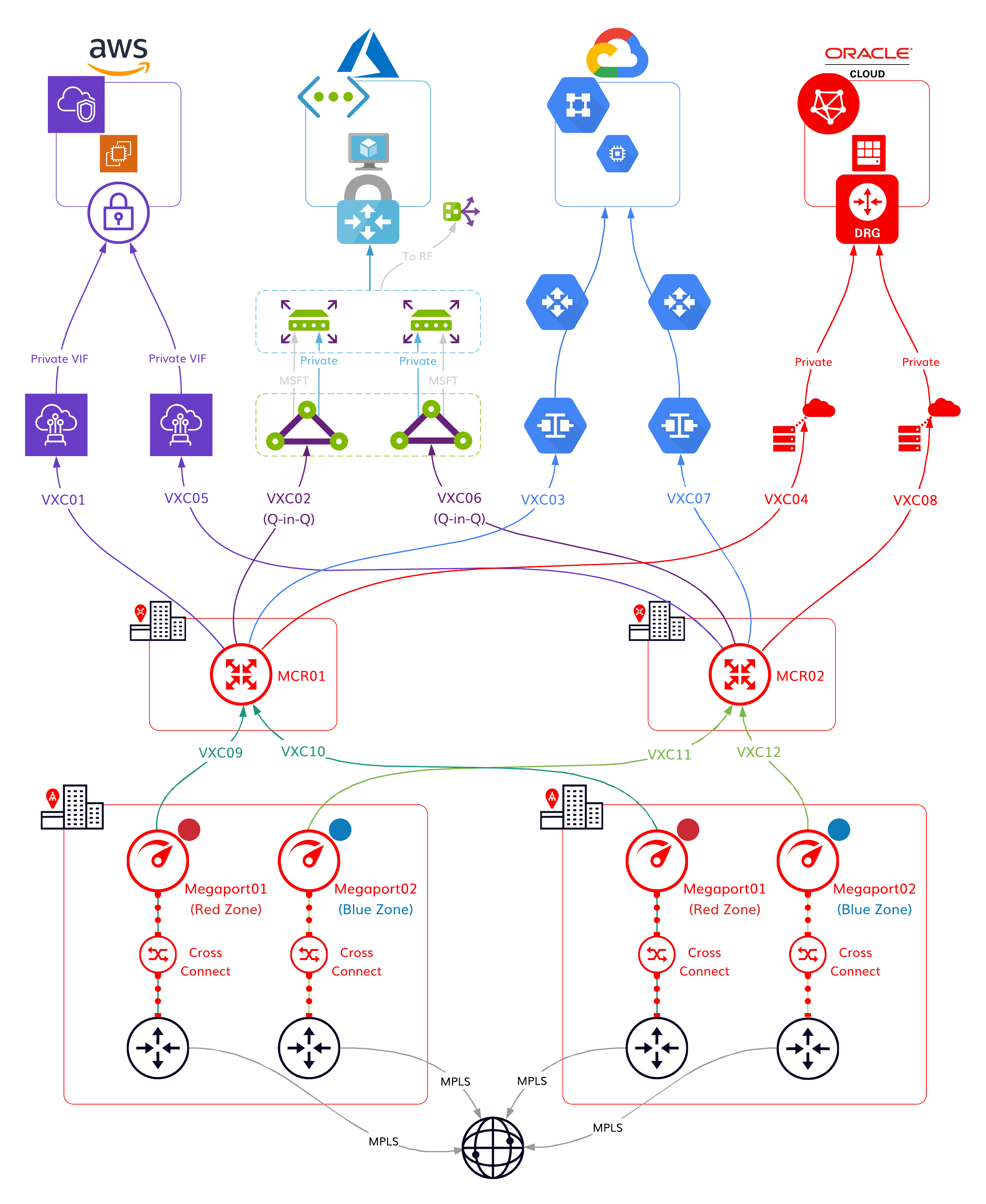
DUAL MCRs as hubs connecting DCs with Megaport in different Diversity Zones in each DC, and CSPs in HA configuration

Multicloud connectivity solutions, all in one place – find the one best for you here.
Want to create your own network designs based on Steve’s work in the diagrams above? Design and build a better network with our free Visio multicloud network diagrams.
We plan to cover more multicloud scenarios and design approaches in future blog posts. Stay tuned.
此内容由惯性聚合(RSS阅读器)自动聚合整理,仅供阅读参考。 原文来自 — 版权归原作者所有。